Method For Producing Negative Electrode For Lithium Secondary Battery

a secondary battery and negative electrode technology, applied in the manufacturing process of electrodes, cell components, electrochemical generators, etc., can solve the problems of poor cycle characteristic, no advantageous effect, and low initial efficiency peculiar to the sio negative electrode, so as to improve the cycle characteristic, theoretical capacity of the thin film is large, and the cycle characteristic is improved

Inactive Publication Date: 2008-04-24
OSAKA TITANIUM TECHNOLOGIES
View PDF3 Cites 14 Cited by
  • Summary
  • Abstract
  • Description
  • Claims
  • Application Information

AI Technical Summary

Benefits of technology

[0014] On the basis of such findings, the inventors filed Japanese Patent Applications (Japanese Patent Application Nos. 2003-123939 and 2003-295363). At the same time, the inventors tackled a further improvement in the thin film type SiO negative electrode wherein a dense thin film of SiO is formed on the surface of a current collector. As a result, the following facts have been made clear.
[0015] The theoretical capacity of a SiO thin film is large. Needless to say, however, as the film thickness thereof is larger, the film is more preferred. This is because the negative capacity per unit area becomes large in proportion to an increase in the film thickness. However, when the film thickness of the SiO thin film becomes 5 μm or more, in particular 10 μm or less, the cycle characteristic becomes poor. This appears to be because peeling of the SiO thin film advances as the battery is repeatedly charged and discharged. Thus, the i

Problems solved by technology

However, when the film thickness of the SiO thin film becomes 5 μm or more, in particular 10 μm or less, the cycle characteristic becomes poor.
However, the initial efficiency peculiar to the SiO negative electrode lowers remarkably.
However, in the ca

Method used


Image

  • Method For Producing Negative Electrode For Lithium Secondary Battery
  • Method For Producing Negative Electrode For Lithium Secondary Battery
  • Method For Producing Negative Electrode For Lithium Secondary Battery

Examples


examples

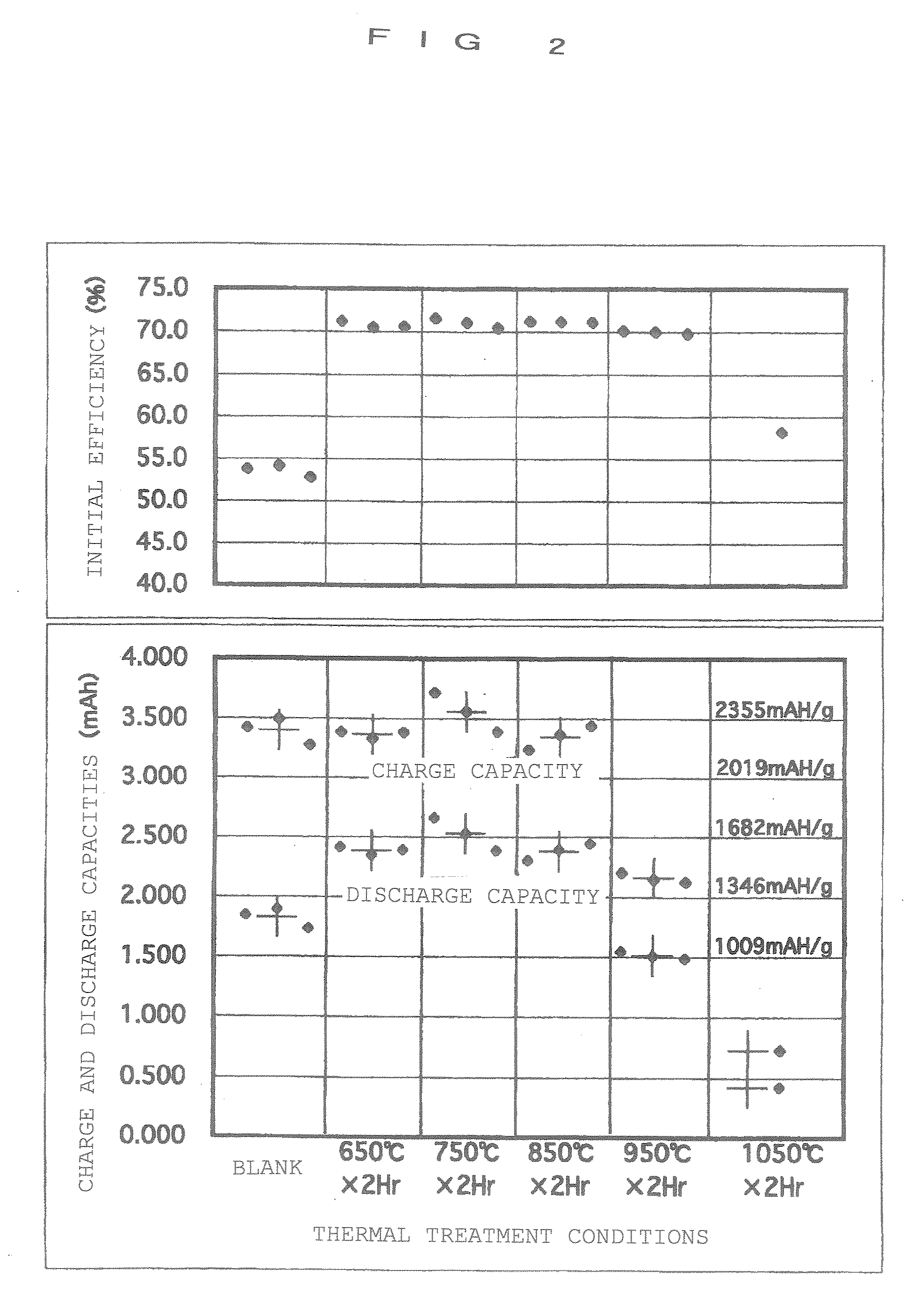
[0054] The following will describe results obtained by examining effects of the structure of the negative electrode in this lithium secondary battery and the production process thereof onto performances of the battery.

[0055] To produce the above-mentioned negative electrode, a rolled copper foil (thickness: 10 μm, and surface roughness: Rz−3 Pa (10−5 torr)]. The mole ratio of O to Si in the formed SiO thin film was 0.50. The film thickness in the specification is a value obtained by assuming that a film is formed on a flat face, and then making a calculation from the weight of the adhesion.

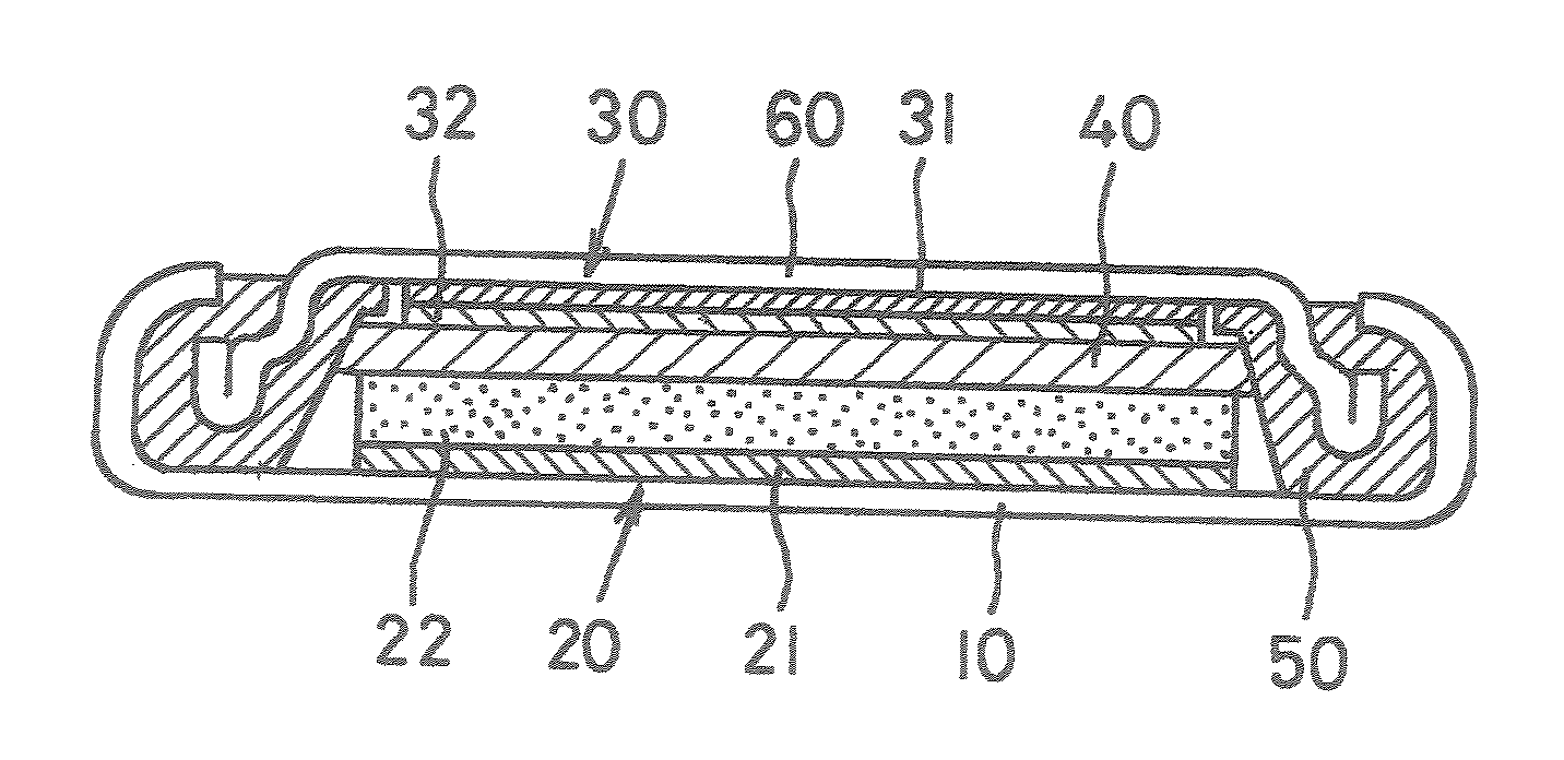
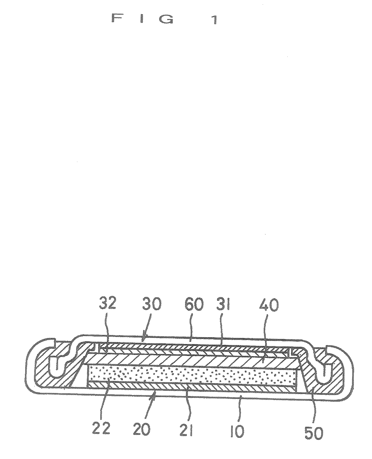
[0056] The thus-produced thin film type SiO negative electrode (1) was combined with a positive electrode, and the combination was sealed together with an electrolytic solution into a case to complete the above-mentioned lithium secondary battery (size diameter: 15 mm, and thickness: 3 mm). LiCoO2 fine powder was used for the positive electrode, and a nonaqueous electrolyte containing ethylene c...


PUM

PropertyMeasurementUnit
Temperatureaaaaaaaaaa
Thicknessaaaaaaaaaa
Thicknessaaaaaaaaaa

Abstract

The lowness of the initial efficiency which is a drawback of lithium secondary batteries wherein a SiO negative electrode is used is largely made better without hindering a large initial charge capacity peculiar to the lithium secondary batteries. A fall in the cycle characteristic when the thickness of the SiO layer is made large is prevented. To realize these matters, a thin film of SiO is formed, as a negative electrode active material layer, on the surface of a current collector by vacuum evaporation or sputtering. The film is preferably formed by an ion plating process. The thickness of the SiO thin film is set to 5 μm or more. The surface roughness of the current collector is set to follows: the maximum height roughness Rz=5.0 or more. After the formation of the thin film, the film is thermally treated in a nonoxidative atmosphere.

Description

TECHNICAL FIELD [0001] The present invention relates to a process for producing a negative electrode used in a lithium secondary battery. BACKGROUND ART [0002] The lithium secondary battery, which absorbs and discharges lithium ions to attain charging and discharging, is very frequently used as a power source of OA instruments, in particular, portable information-processing instruments such as a mobile phone, and a personal computer since the battery has characteristics of a high capacity, a high voltage, and a high energy density together. In the lithium secondary battery, lithium ions are shifted from its positive electrode to its negative electrode when the battery is charged. The lithium ions absorbed in the negative electrode are shifted to the positive electrode when the battery is discharged. [0003] As a negative electrode active material (i.e., active material for a negative electrode) which constitutes the negative electrode of a lithium secondary battery, carbon powder is ...

Claims


Application Information

Patent Timeline
IPC IPC(8): B05D5/12H01M4/02H01M4/04H01M4/139H01M4/1391H01M4/36H01M4/48H01M4/485H01M4/52H01M4/525H01M4/64H01M10/0525H01M10/36
CPCH01M4/0426H01M4/1391H01M4/485H01M4/525Y10T29/49115H01M10/0525H01M2004/021H01M2004/027Y02E60/122H01M4/661Y02E60/10H01M4/04H01M4/48H01M4/66
Inventor NATSUME, YOSHITAKEOGASAWARA, TADASHIAZUMA, KAZUOMI
Owner OSAKA TITANIUM TECHNOLOGIES
Why Eureka
Try Eureka