
Protective Film For Polarizing Plate, Method For Preparation Thereof, Polarizing Plate With Antireflection Function, And Optical Article

a technology of protective film and polarizing plate, which is applied in the direction of polarising elements, instruments, synthetic resin layered products, etc., can solve the problems of affecting the performance of the display itself, warpage, deformation or distortion of the liquid crystal display apparatus, and it is difficult to fabricate a display apparatus constantly exhibiting good display performance for a long time. , to achieve the effect of small warpage, less susceptible to warpage, deformation and distortion

Inactive Publication Date: 2008-04-24
ZEON CORP
View PDF3 Cites 25 Cited by
  • Summary
  • Abstract
  • Description
  • Claims
  • Application Information

AI Technical Summary

Benefits of technology

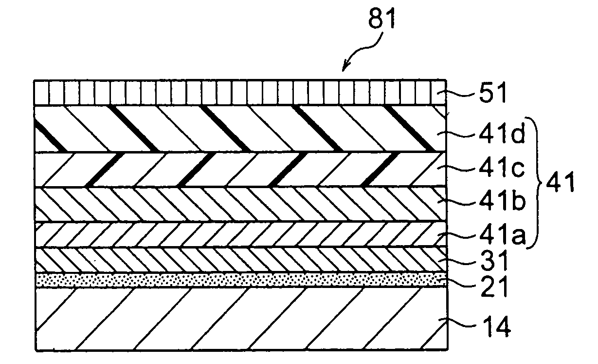
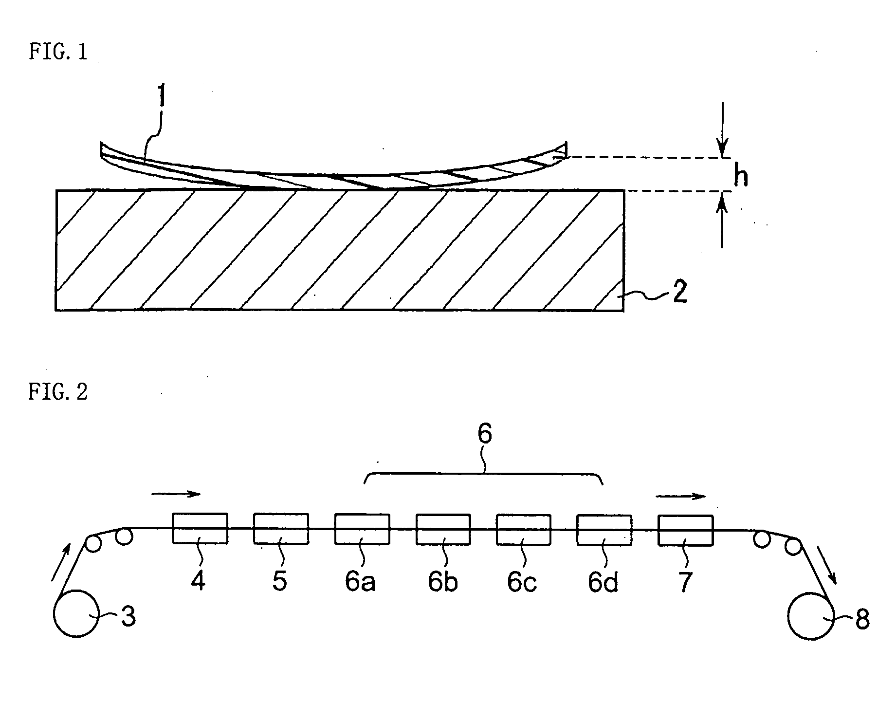
[0008]To achieve the above object, the inventors of the present invention have conducted extensive studies on the protective film for polarizing plate having an antireflection layer on at least one of the surfaces of a substrate film made of a resin material. As a result, the inventors have found that a protective film for polarizing plate with a structure less susceptible to warpage, deformation, and distortion can be obtained by using a resin material having a photoelastic coefficient and a saturated water-absorbing percentage smaller than a specific value and exhibiting only small warpage even when allowed to stand in an atmosphere of high temperature and high humidity for a long period of time. This finding has led to the completion of the present invention.

Problems solved by technology

Such a liquid crystal display apparatus may be warped, deformed, or distorted due to expansion and contraction of the polarizing plates attached to the both sides of the liquid crystal cell according to changes in temperature and humidity, and the like.
This results in deformation of the liquid crystal display apparatus into a propeller-like or other irregular configuration which affects performance of the display itself.
It is difficult to fabricate a display apparatus constantly exhibiting good display performance for a long time.
The moisture hinders uniform forming of an antireflection layer of the film and reduces the quality and productivity.
When the film is laminated with another film in the subsequent step, the curling impairs processability of the film lamination.
The larger the liquid crystal display screen size, the more remarkable the problem.
In regard to performance, the film has a problem of mechanical strength degradation such as peeling due to deformation.

Method used


Image

  • Protective Film For Polarizing Plate, Method For Preparation Thereof, Polarizing Plate With Antireflection Function, And Optical Article
  • Protective Film For Polarizing Plate, Method For Preparation Thereof, Polarizing Plate With Antireflection Function, And Optical Article
  • Protective Film For Polarizing Plate, Method For Preparation Thereof, Polarizing Plate With Antireflection Function, And Optical Article

Examples


preparation example 1

[0124]A mixture containing 7,8-benzotricyclo[4.3.0.12,5]deca-3-ene (trivial name: methanotetrahydrofluorene, hereinafter abbreviated to as MTF), tetracyclo[4.4.0.12,5.17,10]-dodeca-3-ene (trivial name: tetracyclododecene, hereinafter abbreviated to as TCD), and tricyclo[4.3.0.12,5]deca-3,7-diene (trivial name: dicyclopentadiene, hereinafter abbreviated to as DCP) at a weigh ratio of MTF / TCD / DCP=26.8 / 35 / 38.2 was polymerized by a known method of ring-opening polymerization. The resulting polymer was hydrogenated to obtain hydrogenated ring-opening copolymer 1 of MTF, TCD, and DCP. The weight average molecular weight (Mw) of the hydrogenated ring-opening copolymer 1 was 41,000, MWD (=weight average molecular weight / number average molecular weight) was 2.1, the glass transition temperature (Tg) was 136° C., and the melt flow rate was 4.2 g / 10 minutes.

[0125]0.2 part by weight of a phenol-based aging preventive, pentaerythrityltetrakis(3-(3,5-di-tert-butyl-4-hydroxyphenyl)propionate) was ...

preparation example 2

[0126]A mixture of DCP and bicyclo[4.2.1]hept-2-ene (trivial name: norbornene, hereinafter abbreviated to as NB) at a weight ratio of DCP / NB=80 / 20 was polymerized by a known method of ring-opening polymerization. The resulting polymer was hydrogenated to obtain hydrogenated ring-opening copolymer 2 of DCP and NB. Mw of the hydrogenated ring-opening copolymer 2 was 43,000, MWD was 3.2, Tg was 70° C., and the melt flow rate was 23 g / 10 minutes. A forming material in the form of pellets (particles) was prepared from the hydrogenated ring-opening copolymer 2 in the same manner as in Preparation Example 1.

preparation example 3

Preparation of Hard-coat Agent

[0127]30 parts by weight of hexa-functional urethane acrylate oligomer (“NK oligo U-6HA” manufactured by Sin-Nakamura Chemcal Co., Ltd.), 40 parts by weight of butyl acrylates, 30 parts by weight of isobornyl methacrylate (“NK ester IB” manufactured by Sin-Nakamura Chemcal Co., Ltd.), and 10 parts by weight of 2,2-dimethoxy-1,2-diphenylethan-1-on were mixed in a homogenizer to prepare a hard-coat agent.


PUM

PropertyMeasurementUnit
Temperatureaaaaaaaaaa
Lengthaaaaaaaaaa
Lengthaaaaaaaaaa

Abstract

A protective film for polarizing plate having a substrate film of a resin material and, laminated on at least one surface thereof directly or via another layer, an antireflection layer, characterized in that the substrate film has a photoelastic coefficient of less than 9×10⁻¹² Pa−1 and a saturated water-absorbing percentage of less than 0.05%, and the resin material constituting the substrate film exhibits a warpage percentage of 1% or less when the film having an average thickness of 50 μm and a dimension of 100 mm×100 mm is allowed to stand at 60° C. and a humidity of 95% for 500 hours is below 1%; a method for preparing the protective film for polarizing plate; a polarizing plate with antireflection function comprising the protective film and a polarizing plate laminated thereon; and an optical article having the polarizing plate with antireflection function. The above protective film for polarizing plate has a structure which is less susceptible to warpage, deformation, and distortion even when allowed to stand in an atmosphere of high temperature and high humidity for a long period of time.

Description

TECHNICAL FIELD[0001]The present invention provides a protective film for polarizing plate made from a substrate film comprising a resin and an antireflection layer laminated thereon, the resin being less susceptible to warping under high temperature and high humidity conditions and having a small photoelastic coefficient and a small water-absorbing percentage, a method for preparation thereof, a polarizing plate with antireflection function, and an optical article equipped with the polarizing plate.BACKGROUND ART[0002]Conventionally, a liquid crystal display apparatus has been widely used as a displaying unit for table-top calculators, electronic watches, personal computers, word processors, and the like. Such a liquid crystal display apparatus typically has a liquid crystal cell consisting of two sheets of substrates and liquid crystals enclosed and sealed between the substrates. The liquid crystal cell has a structure in which a polarizing plate is attached to one of the surfaces...

Claims


Application Information

Patent Timeline
IPC IPC(8): B32B33/00B05D5/06C25D7/08G02B1/10G02B1/11G02B5/30G02F1/1335
CPCG02B1/105G02B1/11G02F2201/50G02F1/133528G02F2201/38G02B5/3041G02B1/14G02B1/113
Inventor YOSHIHARA, MASANORITOYOSHIMA, TETSUYAYOSHITOMI, YASUMASA
Owner ZEON CORP
Learn More