
Method for obtaining ultra-low NOx emissions from gas turbines operating at high turbine inlet temperatures

Active Publication Date: 2008-05-01
PRECISION COMBUSTION
View PDF12 Cites 1 Cited by
  • Summary
  • Abstract
  • Description
  • Claims
  • Application Information

AI Technical Summary

Benefits of technology

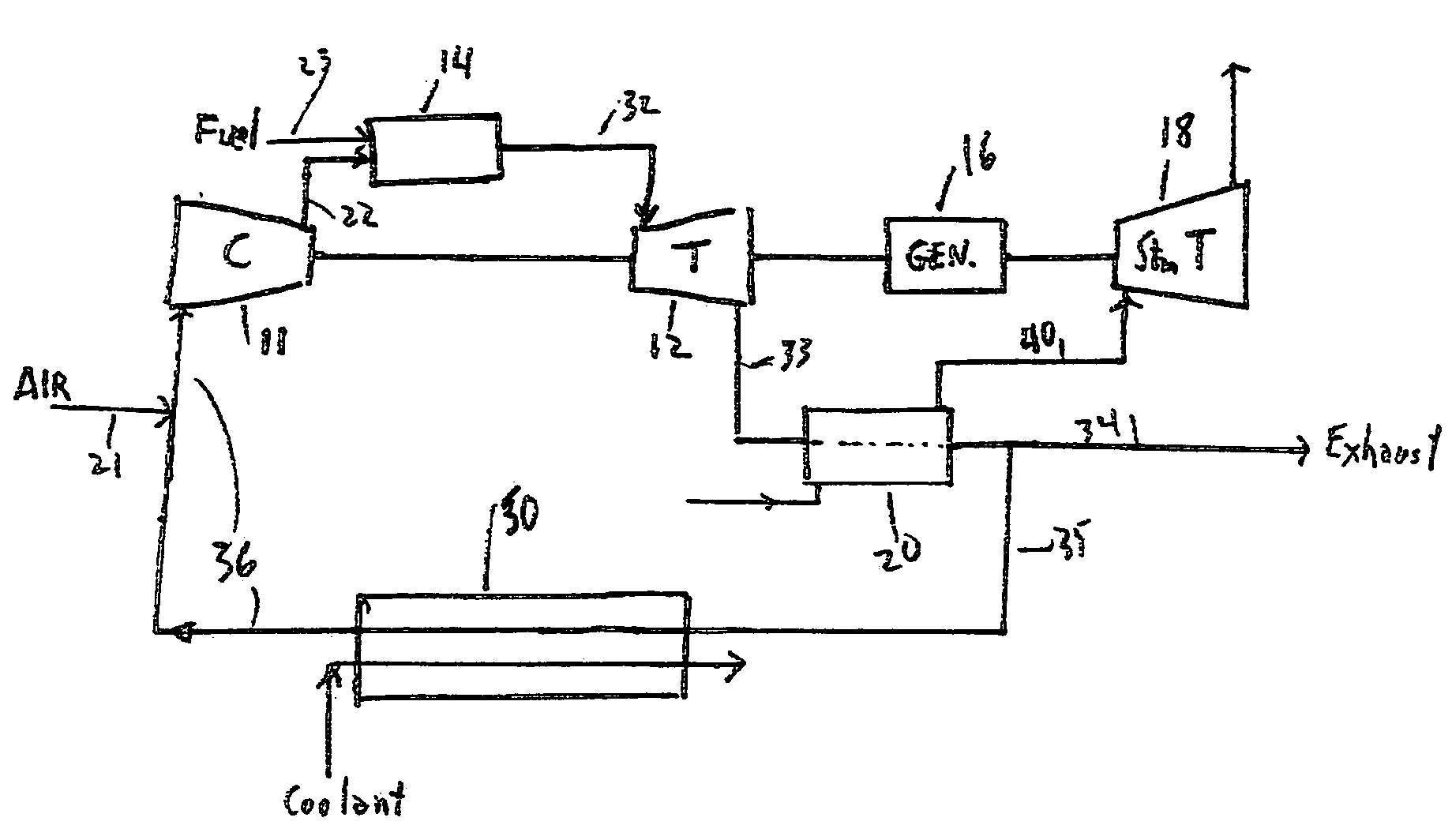
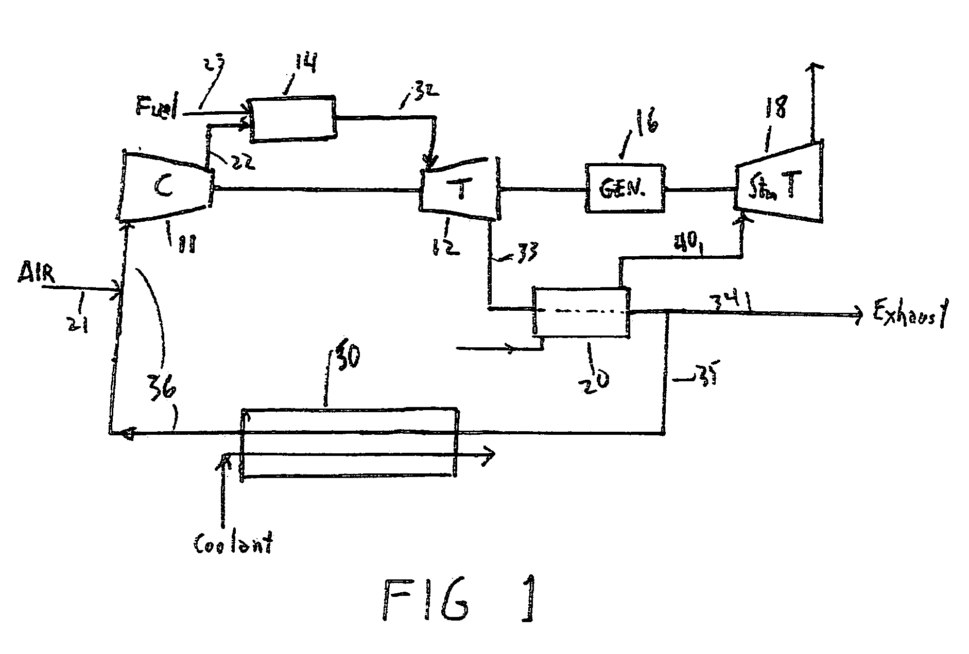
[0011]In a preferred method of the present invention, the inlet air is mixed with cooled combustion product gas prior to entering the compressor of a gas turbine. Optionally, the cooled combustion gases may be compressed separately and then mixed with compressed air exiting the gas turbine compressor. After compression, the compressed air mixture is mixed with fuel and combusted thereby producing hot combustion products that are expanded in the turbine to produce power and hot exhaust gas. The exhaust gas is then transported into a heat recovery unit. Typically, the heat recovery unit comprises a steam boiler in which case the steam may be used for heat or further transported into a steam turbine for additional power production. A portion of the cooled combustion product gases from the heat recovery unit, typically at a temperature of about 100 degrees centigrade, may used to dilute the fresh inlet air. This has the advantage of raising the combustor inlet temperature and improving combustion stability. Preferably however, combustion product gases are further cooled such as to a temperature below about 50 degrees centigrade, as for example by passage through a water spray tower or a secondary heat exchanger before being mixed with the fresh air supplied to the compressor.
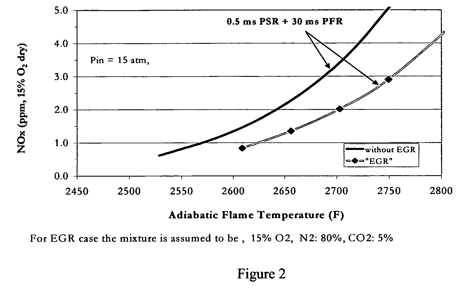
[0013]It is a significant discovery that stable fuel-lean combustion can be achieved in a gas turbine combustor even with a reduction in oxygen content of the combustion air sufficient to significantly reduce the kinetic rate of NOx formation during fuel-lean combustion.

Problems solved by technology

As recognized in the art, hydrocarbon fuels have a limited range of fuel / air ratios within which a flame can propagate.

Method used


Image

  • Method for obtaining ultra-low NOx emissions from gas turbines operating at high turbine inlet temperatures
  • Method for obtaining ultra-low NOx emissions from gas turbines operating at high turbine inlet temperatures
  • Method for obtaining ultra-low NOx emissions from gas turbines operating at high turbine inlet temperatures

Examples


Embodiment Construction

[0016]FIG. 1 depicts a schematic of a typical combined cycle gas turbine system 10 of the present invention. As shown in FIG. 1, combined cycle gas turbine system 10 comprises compressor 11 supplying compressed air to combustor 14 through flow path 22. Fuel 13 enters combustor 14 through flow path 23 wherein it is preferably premixed with the compressed air prior to combustion. Hot combustion products are transported to turbine 12 through flow path 32. Turbine 12 and steam turbine 18 turn and power generator 16. Exhaust gases from turbine 12 are supplied to heat recovery boiler 20 through flow path 33. The steam produced is supplied to steam turbine 18 through flow path 40. The cooled exhaust gases 37 exit through flow path 34 with a portion being supplied to supplemental cooler 50 through flow path 35 for recycle to the compressor 11 inlet through flow path 36. Cooler 50 comprises a heat exchanger further comprising a coolant 38. Fresh air 40 for combustion is added to the recycled...


PUM


Abstract

A method of lowered NOx combustion is taught wherein the kinetic rate of NOx formation is reduced for a given combustion temperature in a gas turbine combustor. A supply of fuel is provided along with a supply of ambient air in sufficient quantity to form a fuel / air mixture having an equivalence ratio greater than about 0.55 when mixed with the fuel. The fuel / air mixture is mixed with a supply of cooled combustion gases in sufficient quantity such that the oxygen content of the resulting air mixture is less than about 18 percent. The resulting air mixture is then passed into the combustor.

Description

CROSS-REFERENCE[0001]This application claims the benefit of PCT International Application No. PCT / US2004 / 017920 filed Jun. 4, 2004, which in turn claimed the benefit of U.S. Provisional Patent Application No. 60 / 476,688 filed Jun. 6, 2003, of which both applications are incorporated herein by reference.FIELD OF THE INVENTION[0002]The present invention relates to a method for improving the thermal efficiency of gas turbine systems by enabling higher firing temperatures without unacceptable NOx production. In particular, the present invention is a method for obtaining low, single-digit NOx emission levels from high turbine-inlet-temperature gas turbines. More particularly, in combined cycle gas turbine systems, the present invention is directed to a method that enables use of higher pressure ratio, higher efficiency gas turbines without sacrificing steam cycle performance thereby providing increased system efficiency.BACKGROUND OF THE INVENTION[0003]With the present awareness of the i...

Claims


Application Information

Patent Timeline
IPC IPC(8): F02C7/26
CPCF02C6/18Y02E20/16F05D2270/082
Inventor PFEFFERLE, WILLIAM C.
Owner PRECISION COMBUSTION
Learn More