Organic electroluminescence device and fabricating method thereof

a technology of organic electroluminescence and fabrication method, which is applied in the direction of discharge tube luminescnet screen, sustainable manufacturing/processing, discharge tube manufacturing, etc., can solve the problems of not being good for mass production of oel device, and not good for reducing production cost either, so as to improve light emission effect and reduce production cost

Inactive Publication Date: 2008-05-01
CHUNGHWA PICTURE TUBES LTD
View PDF22 Cites 24 Cited by
  • Summary
  • Abstract
  • Description
  • Claims
  • Application Information

AI Technical Summary

Benefits of technology

[0009]Accordingly, an objective of the present invention is to provide an OEL device, so as to improve the light emitting effect, solve the problem of light scattering, and reduce the production cost.
[0010]Another objective of the present invention is to provide a method of fabricating the OEL device, so as to solve the problem of generating the air gap between the film layers, and reduce the production cost.
[0042]The OEL device of the present invention adopts the polymeric substrate with the light enhanced structures, so the ray utilization efficiency of the polymeric substrate may be increase. Further, the OEL device adopts the anti-oxidation layer, so as to increase the waterproof function of the polymeric substrate. Moreover, the method of fabricating the OEL device of the present invention fabricates the polymeric substrate by molding method or injection molding method. Therefore, the OEL device can be in mass production so as to lower the production cost. Further, in the fabricating process, the method of fabricating the OEL device may prevent the generation of the air gap, thus avoiding the light scattering.

Problems solved by technology

However, the process of fabricating the microlens array 212 on the glass substrate 210 by RIE is complicated, so it is not good for the mass production of the OEL device 200, and it is not good for reducing the production cost either.

Method used


Image

  • Organic electroluminescence device and fabricating method thereof
  • Organic electroluminescence device and fabricating method thereof
  • Organic electroluminescence device and fabricating method thereof

Examples


first embodiment

The First Embodiment

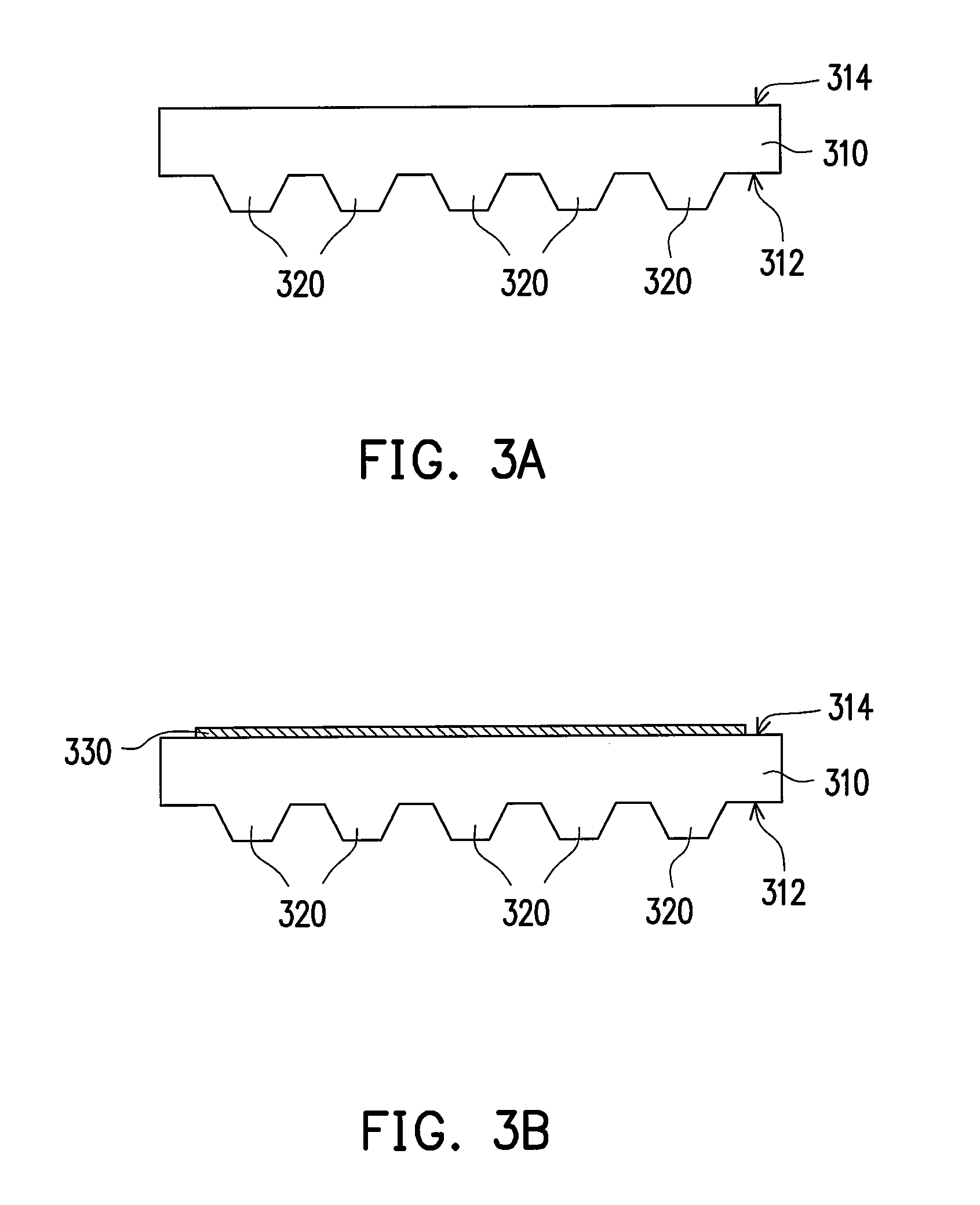
[0053]FIGS. 3A˜3F are schematic sectional views of a flow of fabricating the OEL device of the first embodiment of the present invention. The embodiment is about the fabricating of a bottom emission OEL device.

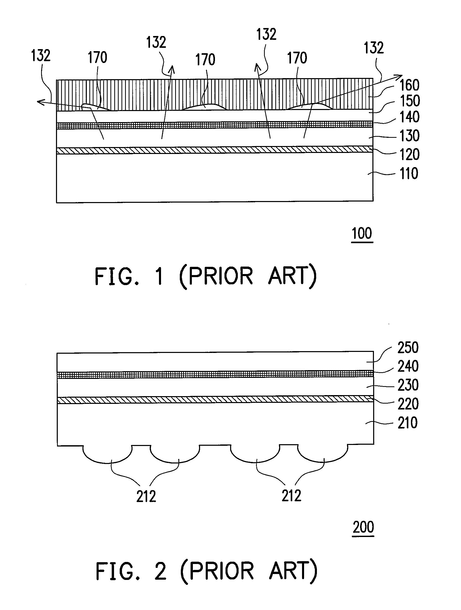
[0054]Referring to FIG. 3A, firstly a polymeric substrate 310 having a first surface 312 and a second surface 314 is provided, wherein a plurality of light enhanced structures 320 is formed on the first surface 312. In the present embodiment, the method of forming the light enhanced structures 320 on the first surface 312 may be molding method or injection molding method. Particularly, the light enhanced structures 320 and the polymeric substrate 310 may be the construction that is integrated as one piece. As compared with the method of fabricating the microlens array 212 by RIE as shown in FIG. 2 in the conventional art, it is easier to fabricate the polymeric substrate 310 with the light enhances structures 320, so it can be in mass production so as to lo...

second embodiment

The Second Embodiment

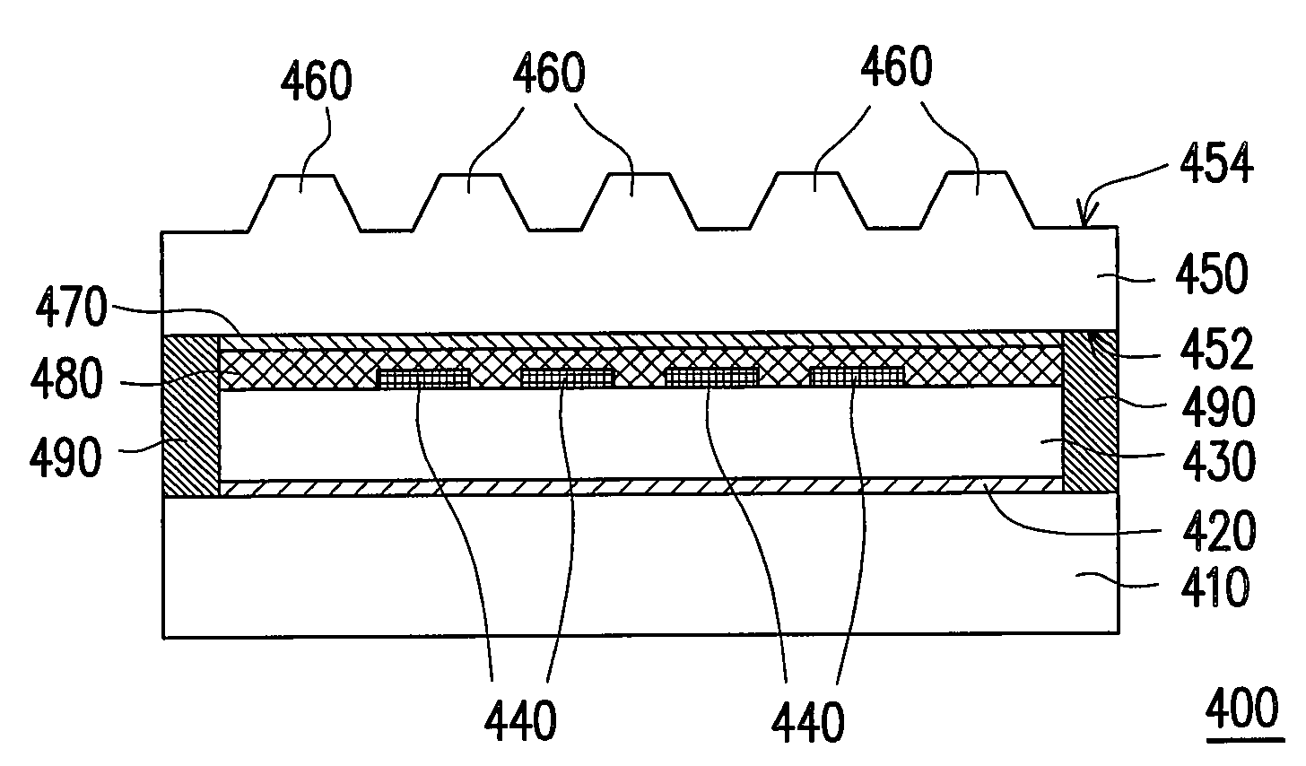
[0066]FIGS. 4A˜4F are schematic sectional views of a flow of fabricating the OEL device of the second embodiment of the present invention. The embodiment is about the fabricating of a top emission OEL device.

[0067]Referring to FIG. 4A, firstly a substrate 410 is provided. The substrate 410 may be a glass substrate, a plastic substrate or another kind of substrate.

[0068]Next, referring to FIG. 4B, a first electrode 420 is formed on the substrate 410. In an embodiment, the method of forming the first electrode 420 may be sputtering, evaporation method or another suitable method. The material of the first electrode 420 is, for example, metal, and the type of the metal is not limited in the present invention.

[0069]Then, referring to FIG. 4C, an organic light emitting layer 430 is formed on the first electrode 420. In an embodiment, the method of forming the organic light emitting layer 430 is, for example, coating method, evaporation method or another suitable metho...

third embodiment

The Third Embodiment

[0077]The third embodiment is similar to the second embodiment. It is also about the fabricating method and the structure of a top mission OEL device. FIG. 5 is a schematic view of the OEL device of the third embodiment of the present invention.

[0078]Referring to FIGS. 4A˜4E and FIG. 5, firstly, in the third embodiment, the steps as shown in FIGS. 4A˜4D are used to fabricate an OEL device having the substrate 410, the first electrode 420, the organic light emitting layer 430 and the second electrode 440. Then, as shown in FIG. 4E, a polymeric substrate 450 is provided.

[0079]It should be noted that the difference between the present embodiment and the second embodiment is that in the third embodiment, the anti-oxidation layer 470 is not formed between the second electrode 440 and the polymeric substrate 450. As shown in FIG. 5, when the anti-oxidation layer 470 is formed on the second surface 454, the polymeric substrate 450 is directly disposed on the second elec...


PUM


Abstract

An organic electroluminescence (OEL) device, having a polymeric substrate, a plurality of light enhanced structures, an anti-oxidation layer, a first electrode, an organic light emitting layer, a second electrode and a protective layer, is provided. The polymeric substrate has a first surface and a second surface. The light enhanced structures are disposed on the first surface. The anti-oxidation layer is disposed on the second surface. The first electrode is disposed on the anti-oxidation layer. The organic light emitting layer is disposed on the first electrode. The second electrode is disposed on the organic light emitting layer. The protective layer is disposed on the second electrode. Since the OEL device has light enhanced structures, not only light efficiency can be improved but also surface scattering is reduced. Moreover, a method of fabricating an OEL device is also provided to make the OEL device in mass production for lowering the production cost.

Description

BACKGROUND OF THE INVENTION[0001]1. Field of Invention[0002]The present invention relates to a light emitting device and a fabricating method thereof, and more particularly to an organic electroluminescence (OEL) device and a fabricating method thereof.[0003]2. Description of Related Art[0004]The OEL device has the features such as self luminescence, wide visual angle, high reply speed, low driving voltage and full color, and recently it may be utilized to be applied in the organic electroluminescence display. Generally speaking, the OEL device comprises an anode, a cathode and an organic light emitting layer located between the two electrodes. When the current passes between the anode and the cathode, and the electrons and the electron holes are combined in the organic light emitting layer to generate the excitons, the organic light emitting layer may generate the light emitting mechanism of different colors according to the material features.[0005]In order to increase the ray util...

Claims


Application Information

Patent Timeline
Patent Type & Authority Applications(United States)
IPC IPC(8): H01L51/50H05B33/00
CPCH01L51/0097Y02E10/549H01L51/5262H01L51/5237H01L51/524H01L51/5253Y02P70/50
Inventor WEI, AN-CHIYANG, BO-RUSHIEH, HAN-PING
Owner CHUNGHWA PICTURE TUBES LTD
Why Eureka
Try Eureka