
Catalyst for cathode of fuel cell, preparing method and fixing method thereof, and fuel cell including same

Inactive Publication Date: 2008-05-01
WASEDA UNIV +1
View PDF12 Cites 9 Cited by
  • Summary
  • Abstract
  • Description
  • Claims
  • Application Information

AI Technical Summary

Benefits of technology

[0011]An exemplary embodiment of the present invention provides a cathode catalyst for a fuel cell, which is inexpensive and has high durability against methanol, a method of manufacturing and fixing it, and a fuel cell including it.
[0018]According to the embodiment of the present invention, a cathode catalyst may be selected from the group consisting of PdSn, PdAu, PdCo, PdWO3, and mixtures thereof, and may have a superior oxidant reduction characteristic relative to a conventional platinum catalyst in an alkaline aqueous solution, and particularly in an alkaline aqueous solution with a high methanol concentration, considering the influence of methanol crossover through a solid polymer electrolyte membrane. In addition, it can selectively reduce an oxidant, even if methanol crossover from an anode to a cathode occurs, and therefore it can work with a fuel with a high concentration. It can also have excellent oxidant reduction performance, even when an alkaline aqueous solution including methanol is supplied as an oxidant and selectively reduced. Furthermore, since it may have less deteriorated oxidant reduction performance under methanol than a conventional catalyst, methanol can be supplied in a high concentration at an anode of a DMFC, accomplishing high energy density of a fuel cell.
[0029]According to the manufacturing method, a cathode catalyst cannot be cohered but is easily prepared into ultrafine particles with a nanometer size and high dispersion. The cathode catalyst can accomplish high reduction efficiency.
[0030]According to still another embodiment of the present invention, a method of fixing a cathode catalyst for a fuel cell comprises: radiating ultrasonic waves into an aqueous solution, including a metal source selected from the group consisting of metal ions, metal-containing ions, and mixtures thereof, an organic acid, and a water-soluble organic compound; producing catalyst particles, including a metal, by reducing the metal ions or the metal-containing ions with radicals produced by the ultrasonic waves; and fixing the catalyst particles on the surface of an electrode by impregnating the electrode with a mono-molecular film of an organic silane compound on the surface thereof with a solution wherein the catalyst particles are produced. According to the fixing method, an electrode can be prepared to have a cathode catalyst fixed on the surface thereof. The surface has a high degree of flatness, with surface roughness (Ra) of less than 10 nm. Accordingly, the electrode can accomplish high reduction activity due to the cathode catalyst on the surface thereof.
[0031]Since the electrode fixed with a cathode catalyst with high flatness has a structure of nanoparticles piled up one by one, unlike a membrane-type electrode, it has a relatively larger surface area, thereby increasing catalyst activity.
[0032]In general, nanoparticles are prepared in an impregnation method or a thermal reduction method. However, the impregnation method requires inclusion of a reducing agent for preparing the nanoparticles, and therefore requires an additional process to remove the reducing agent or its byproduct. On the other hand, the thermal reduction method requires a high temperature device so that nanoparticles can not only be easily synthesized but are also cohered. Therefore, the present invention provides an ultrasonic wave method in which ultrasonic waves are radiated into an aqueous solution to cause cavitation, and hydrogen radicals (H.) produced as a result can be used as a reducing agent. This method needs no reducing agent, and accordingly eliminates the need to remove the reducing agent or its byproduct, making it possible to easily prepare nanoparticles by only radiating ultrasonic waves.

Problems solved by technology

However, since platinum is in limited supply and is expensive, it has been difficult to put to practical use.
Accordingly, practical use thereof is still premature until it can be easily synthesized and have a controllable particle size.
However, this method has a problem of easy coherence of a metal when more metal is supported.
However, the organic metal complex has been found to have a problem of stability.
In addition, NAFION®, which is widely used as an electrolyte membrane of a DMFC, has a problem in that methanol as a fuel for the DMFC permeates through the solid polymer electrolyte membrane and reaches the cathode, and is then non-electrochemically oxidized at the cathode, resulting in methanol waste as well as poisoning of an oxygen reduction catalyst which deteriorates catalyst activity.

Method used


Image

  • Catalyst for cathode of fuel cell, preparing method and fixing method thereof, and fuel cell including same
  • Catalyst for cathode of fuel cell, preparing method and fixing method thereof, and fuel cell including same
  • Catalyst for cathode of fuel cell, preparing method and fixing method thereof, and fuel cell including same

Examples


example 1

[0074]10 ml of ethanol was added to 100 mL of an aqueous solution including 0.2 mmol / L (NH4)2PdCl4, 0.2 mmol / L SnCl2.2H2O, and 4 mmol / L citric acid. 150 mL of the resulting aqueous solution was put in a glass beaker and then radiated with ultrasonic waves at 20 kHz and 55 W (42 W / cm2) at a temperature of 25±2° C. for 2 hours by using a Sonifier 450D (Branson Co.), producing PdSn alloy nanoparticles.

[0075]The produced PdSn alloy nanoparticles were measured with respect to their atomic ratio of Pd and Sn by using X-ray photoelectron spectroscopy (XPS). The result was Pd70Sn30.

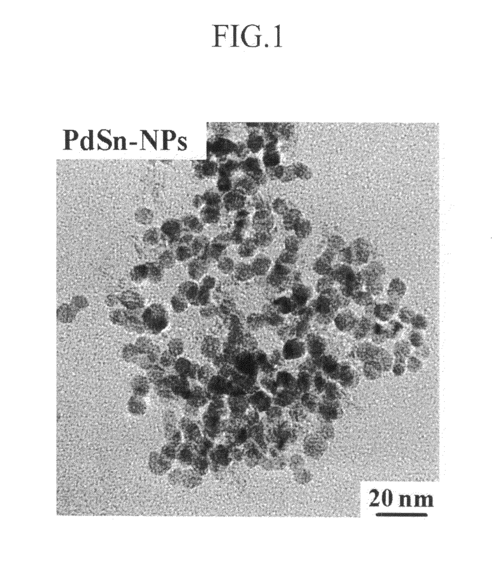
[0076]In addition, they were examined with a transmission electron microscope (TEM). The result is shown in FIG. 1.

[0077]As shown in FIG. 1, the particles turned out to have a particle diameter ranging from 8 to 10 nm based on the TEM.

example 2

[0078]PdAu alloy nanoparticles were prepared according to the same method as in Example 1, except that NaAuCl4.2H2O instead of SnCl2.2H2O was included.

[0079]Then, they were measured with respect to their atomic ratio of Pd and Sn by using X-ray photoelectron spectroscopy (XPS) according to the same method as in Example 1. The result was Pd85Au15.

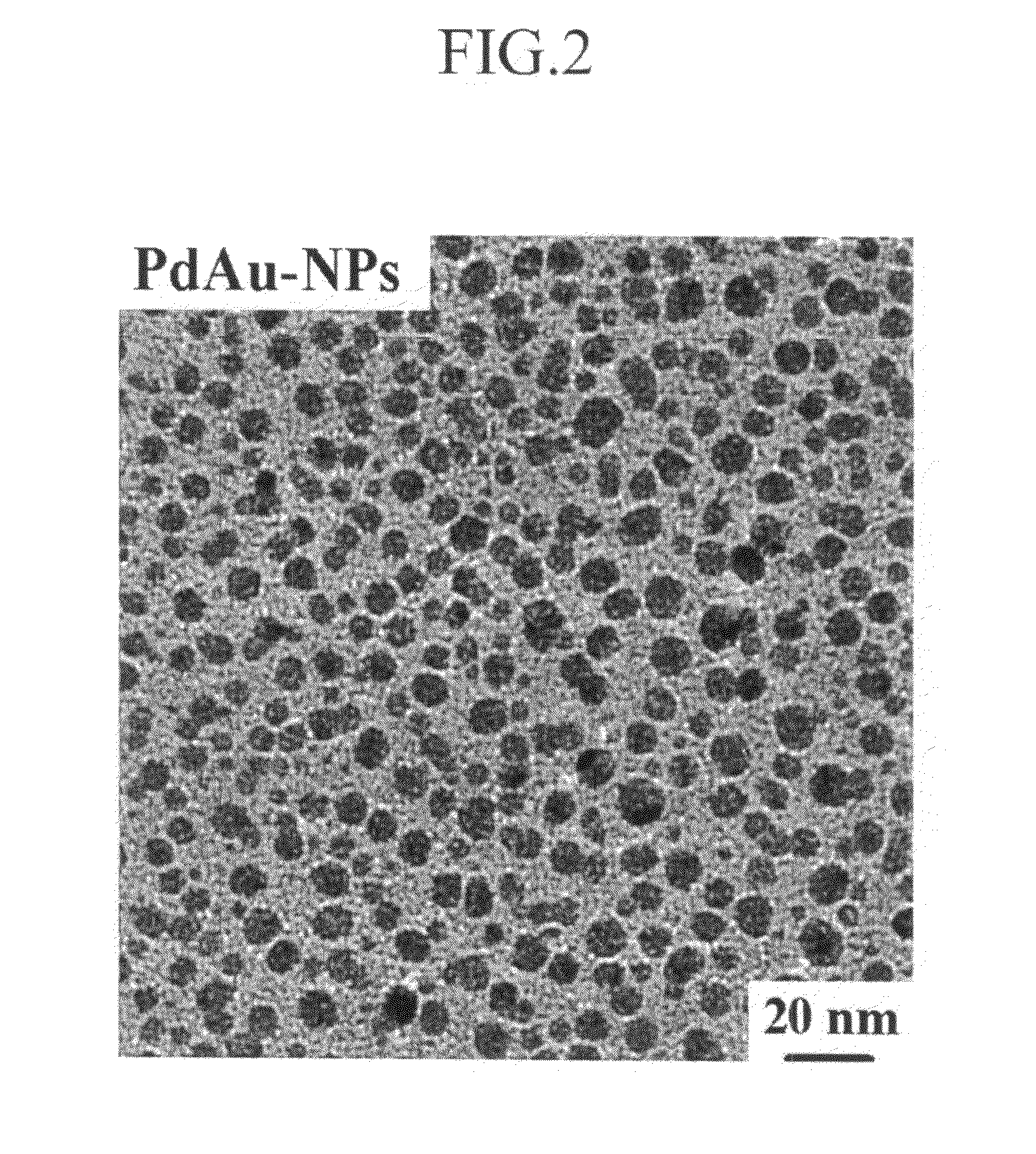
[0080]In addition, they were examined by using a transmission electron microscope (TEM). The result is shown in FIG. 2.

[0081]As shown in FIG. 2, the PdAu alloy nanoparticles had a particle diameter of 6 to 7 nm based on the TEM.

example 3

[0082]PdCo alloy nanoparticles were produced according to the same method as in Example 1, except that CoSO4.7H2O instead of SnCl2.2H2O was included.

[0083]Then, the PdCo alloy nanoparticles were measured with respect to atomic ratio of Pd 4 and Co by using X-ray photoelectron spectroscopy (XPS) according to the same method as in Example 1. The result was Pd95CO5.

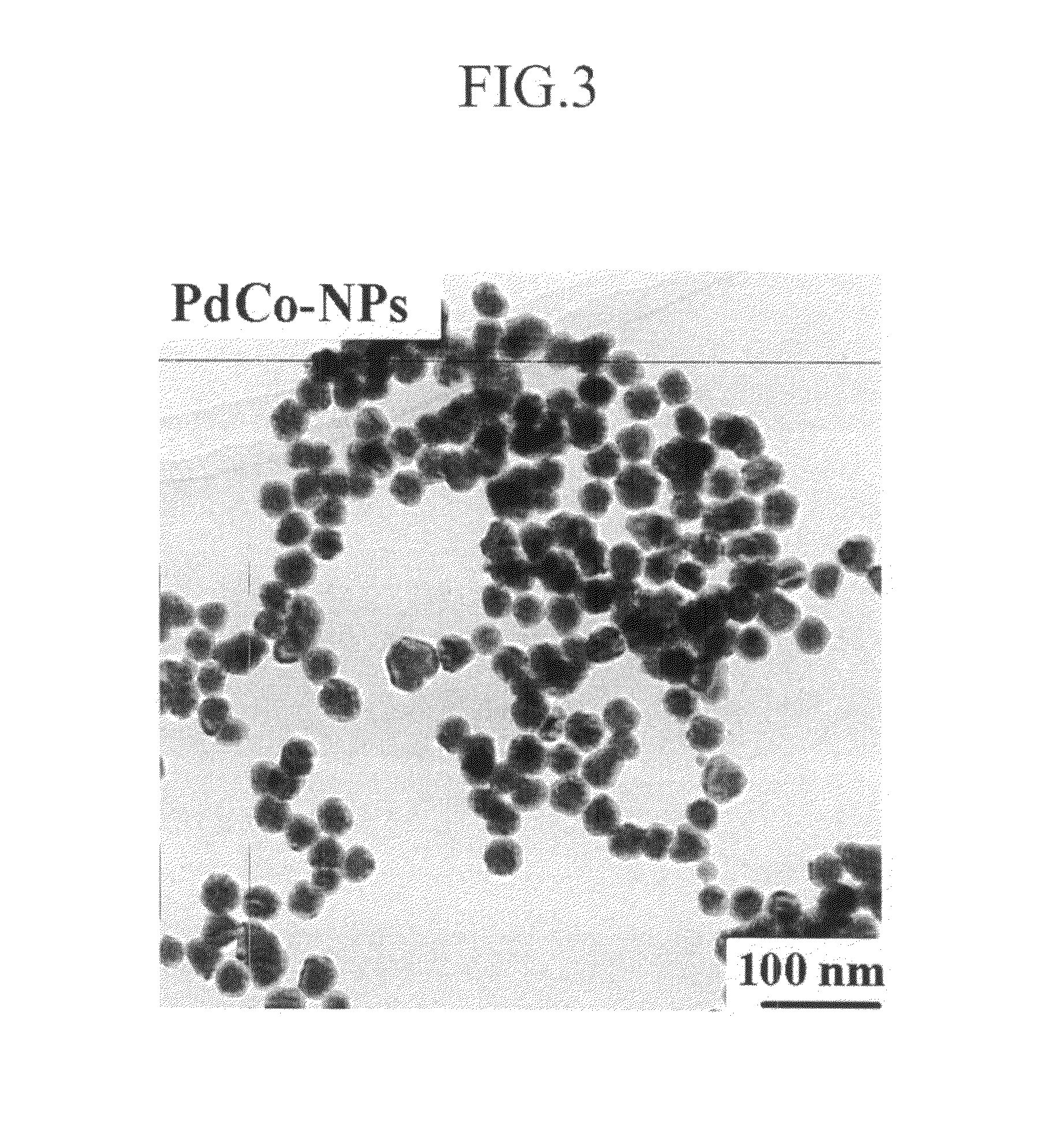
[0084]In addition, they were examined by using a TEM. The result is shown in FIG. 3.

[0085]As shown in FIG. 3, they had a particle diameter of 30 nm based on the TEM.


PUM


Abstract

A cathode catalyst for a fuel cell is inexpensive and has high durability against methanol. A method of manufacturing and fixing the cathode catalyst, and a fuel cell including it, are disclosed. The cathode catalyst includes a compound selected from the group consisting of PdSn, PdAu, PdCo, PdWO3, and mixtures thereof. The present invention can provide a non-platinum-based cathode catalyst as a substitute for a platinum catalyst, the cathode catalyst having a low cost and improved catalyst activity, thereby contributing to popular use of a fuel cell. In addition, since the cathode catalyst of the present invention has high durability against methanol and can thereby be used with a fuel in a high concentration, it can increase the energy density of a direct methanol fuel cell (DMFC).

Description

CLAIM OF PRIORITY[0001]This application makes reference to, incorporates the same herein, and claims all benefits accruing under 35 U.S.C.§119 from an application for CATALYST FOR CATHODE OF FUEL CELL, PREPARING METHOD AND FIXING METHOD THEREOF, AND FUEL CELL INCLUDING SAME earlier filed in the Japanese Intellectual Property Office on the 26th of Oct. 2006 and there duly assigned Serial No. 2006-291198.BACKGROUND OF THE INVENTION[0002]1. Technical Field[0003]The present invention relates to a cathode catalyst for a fuel cell. More particularly, the present invention relates to a novel cathode catalyst which can replace a conventional platinum catalyst, a method of preparing and supporting the same, and a fuel cell including the same.[0004]2. Related Art[0005]Since a direct methanol fuel cell (DMFC) including a solid polymer electrolyte does not need additional devices such as a reformer and the like, it has received attention as a future small electric power source. Generally, a DMF...

Claims


Application Information

Patent Timeline
IPC IPC(8): H01M4/86H01M4/88
CPCH01M4/8846H01M4/921Y02E60/50H01M8/1011H01M2004/8689H01M4/923Y02P70/50H01M4/90H01M4/88
Inventor OSAKA, TETSUYAMOMMA, TOSHIYUKIPARK, JONG-EUN
Owner WASEDA UNIV
Learn More