Refining and casting apparatus and method

a technology of refining and casting apparatus and preforms, which is applied in the direction of casting apparatus, metal-working apparatus, manufacturing tools, etc., can solve the problems of difficult production, difficult to achieve cooling rate, and prone to segregation of metals, so as to reduce the possibility of recontamination of melts and increase process efficiency

Active Publication Date: 2008-05-22
ATI PROPERTIES LLC
View PDF100 Cites 26 Cited by
  • Summary
  • Abstract
  • Description
  • Claims
  • Application Information

AI Technical Summary

Benefits of technology

[0016]In various embodiments, the base of the mold can be moved relative to the side wall along an axis. In these embodiments, the base can be moved downwardly with respect to the side wall in order to withdraw the preform as it is being created. As a result, longer preforms can be created and the nucleated casting process can be interrupted less often, thereby potentially increasing the efficiency of the process. In various circumstances, portions of the droplet spray, i.e., the overspray, may accumulate on a top surface of the mold side wall. In some instances, the overspray accumulated on the side wall may bond with the preform preventing or inhibiting the preform from being moved relative to the side wall. In these circumstances, the nucleated casting process may have to be stopped in order to remove the overspray. Alternatively, in various embodiments, the atomizing nozzle can be oriented such that the droplet spray passes over the top of the side wall and thereby remelts and removes at least a portion of the overspray that has accumulated thereon. In embodiments having only one atomizing nozzle, for example, overspray accumulated on some regions of the side wall top surface may not be removed by the droplet spray. In certain embodiments

Problems solved by technology

Metallic materials prone to segregation, however, are difficult to produce in large diameters by VAR melting, the last step in the triple melt sequence, because it is difficult to achieve a cooling rate that is sufficient to minimize segregation.
Although solidification microsegregation can be minimized by subjecting cast ingots to lengthy homogenization treatments, such treatments are not totally effective and may be costly.
In addition, VAR often will introduce macro-scale defects, such as white spots, freckles, center segregation, etc., into the ingots.
In some cases, large diameter ingots are fabricated into single components, so VAR-introduced defects cannot be selectively removed prior to component fabrication.
Consequently, the entire ingot or a portion of the ingot may need to be scrapped.
Thus, disadvantages of the triple melt technique may include large yield losses, lengthy cycle times, high materials processing costs, and the inability to produce large-sized ingots of segregation-prone metallic materials of acceptable metallurgical quality.
Spray forming suffers from a number of disadvantages that make its application to the formation of large diameter preforms problematic.
An unavoidable byproduct of spray forming is overspray, wherein the me

Method used


Image

  • Refining and casting apparatus and method
  • Refining and casting apparatus and method
  • Refining and casting apparatus and method

Examples


example 1

Computer Simulation

[0053]Computer simulations show that preforms prepared by the apparatus 10 of the invention will cool significantly faster than ingots produced by conventional processing. FIG. 3 (mass flow rate to caster of 0.065 kg / sec. or about 8.5 lb / min.) and FIG. 4 (mass flow rate to caster of 0.195 kg / sec.) illustrate the calculated effects on the temperature and liquid volume fraction of a preform cast by the apparatus 10 of the present invention using the parameters shown in Table 1 below.

TABLE 1Parameters of Simulated CastingsPreform GeometryCylindrical 20 inch (508 mm) preform diameterInflow region constitutes entire top surface of preformNucleated Casting Apparatus Operating ConditionsMass flow rates of 0.065 kg / sec. (as reported in the reference of footnote1 below for a comparable VAR process) (FIG. 3) and 0.195 kg / sec.(FIG. 4) 324° K (51° C.) average temperature of the cooling water in themold.324° K (51° C.) effective sink temperature for radiation heat loss from th...

example 2

Trial Casting

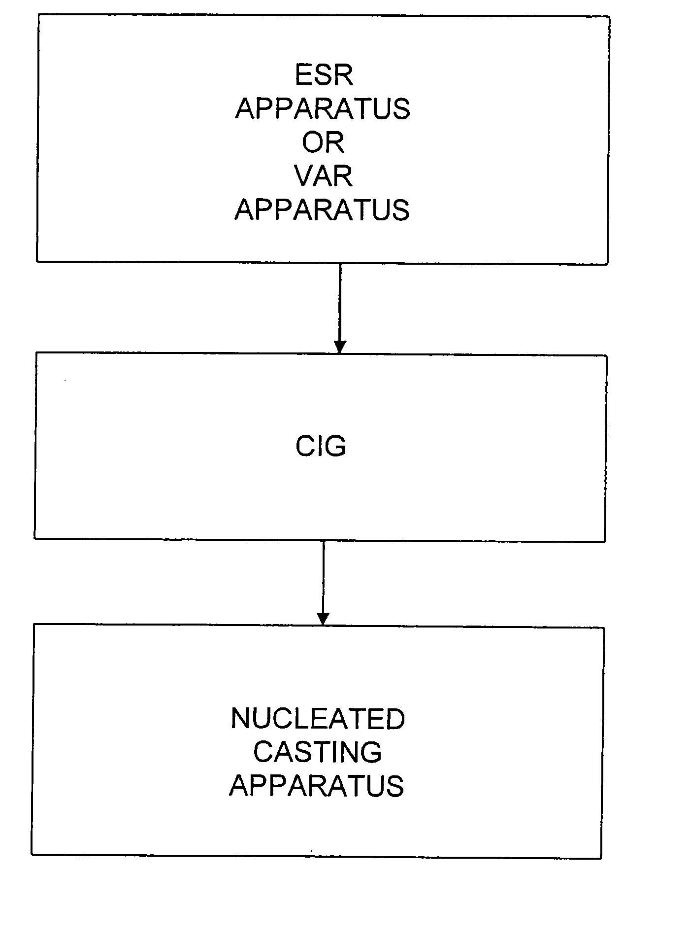
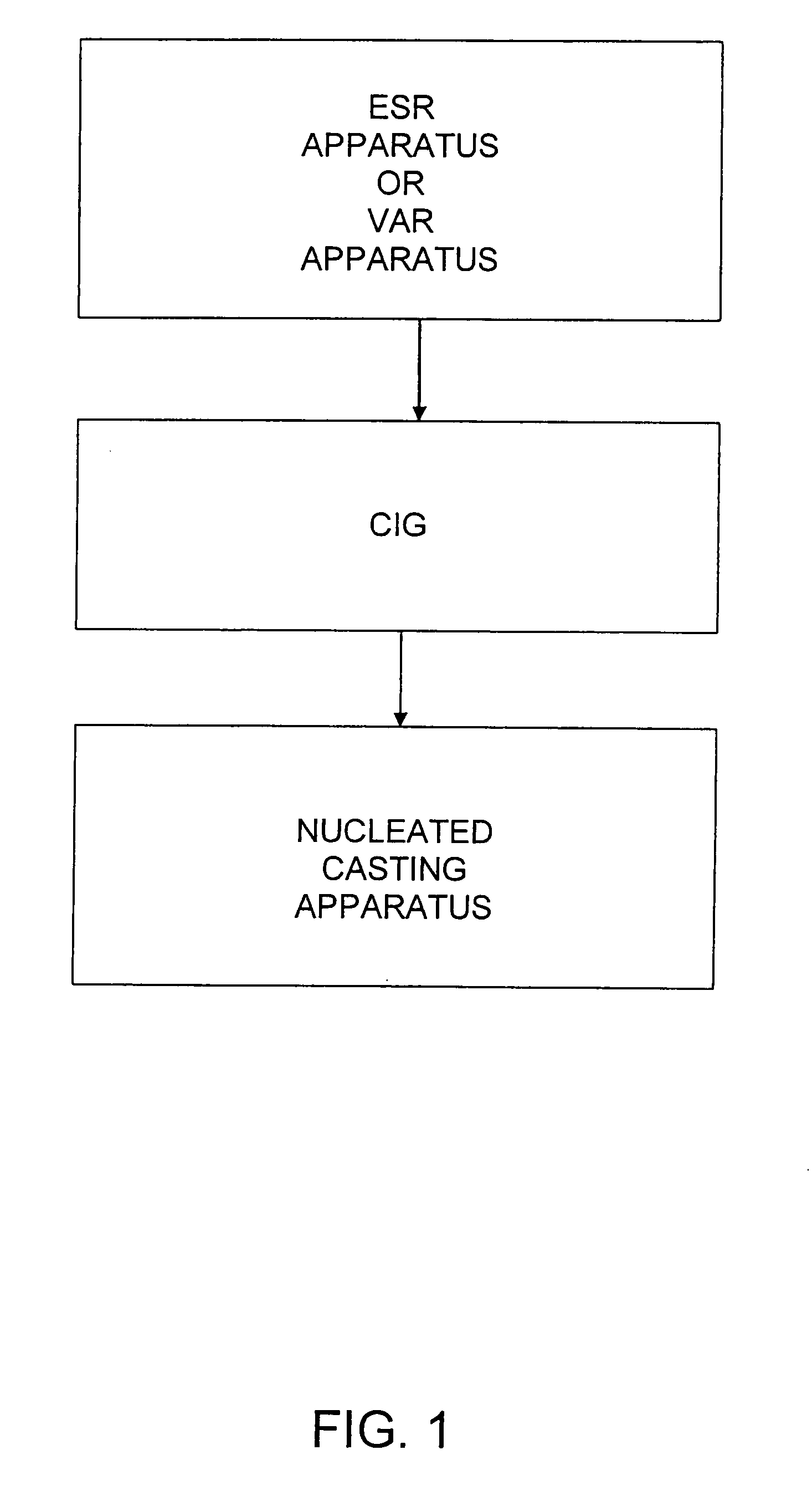
[0056]A trial casting using an apparatus constructed according to the invention was performed. The apparatus 100 is shown schematically in FIG. 5 and, for purposes of understanding its scale, was approximately thirty feet in overall height. The apparatus 100 generally included ESR head 110, ESR furnace 112, CIG 114, nucleated casting apparatus 116, and material handling device 118 for holding and manipulating the mold 120 in which the casting was made. The apparatus 100 also included ESR power supply 122 supplying power to melt the electrode, shown as 124, and CIG power supply 126 for powering the induction heating coils of CIG 114.

[0057]ESR head 110 controlled the movement of the electrode 124 within ESR furnace 112. ESR furnace 124 was of a typical design and was constructed to hold an electrode of approximately 4 feet in length by 14 inches in diameter. In the case of the alloy used in the trial casting, such an electrode weighed approximately 2500 pounds. ESR furnac...


PUM

PropertyMeasurementUnit
Temperatureaaaaaaaaaa

Abstract

An apparatus for casting metals by a nucleated casting technique to create a preform, the apparatus including a mold having a base and a side wall where the base can be moved relative to the side wall to withdraw the preform as it is being created. In various circumstances, portions of a droplet spray created by an atomizing nozzle, i.e., overspray, may accumulate on a top surface of the side wall and prevent or inhibit the preform from being moved relative to the side wall. The atomizing nozzle can be oriented such that the droplet spray passes over the top of the side wall to remelt and remove at least a portion of the overspray that has accumulated thereon. The mold can be rotated such that the overspray formed on a region of or on the entire perimeter of the top surface can pass through the droplet spray and can be removed from the side wall.

Description

CROSS REFERENCE TO RELATED APPLICATIONS[0001]The present application is a continuation-in-part application claiming priority under 35 U.S.C. § 120 from co-pending U.S. patent application Ser. No. 11 / 564,021, entitled REFINING AND CASTING APPARATUS AND METHOD, filed on Nov. 28, 2006, which is a continuation application of U.S. patent application Ser. No. 10 / 158,382, entitled REFINING AND CASTING APPARATUS, filed on May 30, 2002, now U.S. Pat. No. 7,154,932, which is a continuing application of U.S. patent application Ser. No. 09 / 726,720, entitled REFINING AND CASTING APPARATUS AND METHOD, filed on Nov. 15, 2000, now U.S. Pat. No. 6,496,529, the entire disclosures of which are hereby incorporated by reference herein.STATEMENT REGARDING FEDERALLY SPONSORED RESEARCH OR DEVELOPMENT[0002]Certain of the research leading to the present invention was funded by the National Institute of Standards and Technology Advanced Technology Program (NIST ATP), Contract No. 70NANB1H3042. The United Stat...

Claims


Application Information

Patent Timeline
IPC IPC(8): B22D23/00B22D45/00
CPCB22D23/003
Inventor FORBES JONES, ROBIN M.SHAFFER, STERRY A.
Owner ATI PROPERTIES LLC
Why Eureka
Try Eureka