Methods for Detecting Contaminants in a Liquid

a technology of liquid contaminants and apparatus, applied in the direction of instruments, nuclear elements, greenhouse gas reduction, etc., can solve the problems of poor selectivity, large sample preparation or limited methods, corrosion and other problems in the fluid handling system of the reactor

Inactive Publication Date: 2008-05-22
GENERAL ELECTRIC CO
View PDF21 Cites 57 Cited by
  • Summary
  • Abstract
  • Description
  • Claims
  • Application Information

AI Technical Summary

Problems solved by technology

The ultrapure water can comprise contaminants, which cause corrosion and other problems in the reactors fluid handling system.
Unfortunately, these methods can require extensive sample preparation or are limited by poor selectivity, inadequate detection limits, interference effects, baseline drift, and contamination during sampling or handling.
IC methods originally comprised column ion exchange chromatography, which required large sample volumes, wet chemical analysis of collected fractions, and took hours to perform.
However, modern IC methods still suffer from disadvantages that make their use impractical in many situations, such as expense, complexity, and maintenance.
Furthermore, the IC's currently attain an analysis time of approximately ten minutes, which is still too long in many applications.
Inductively coupled plasma-isotope dilution mass spectrometry (ICP-IDMS) is suitable as a routine method for trace element and element speciation analysis; however, it is limited by the lack of commercially available isotope-labeled spike compounds for species-specific isotope dilution and by the complicated system set-up required for species-unspecific ICP-IDMS analysis.
CE also has its limitations, e.g., there are practical limits to the amount of voltage that can be applied and to the shortness of the capillary tube.
Additionally, the heating of the electrolyte in the tube due to extremely high voltage gradients causes problems, such as undesirable zone broadening or even boiling of the electrolyte and a total breakdown of the electrophoretic process.
Such limitations make the use of capillary zone electrophoresis impractical for many applications.

Method used


Image

  • Methods for Detecting Contaminants in a Liquid
  • Methods for Detecting Contaminants in a Liquid
  • Methods for Detecting Contaminants in a Liquid

Examples


experiment 1

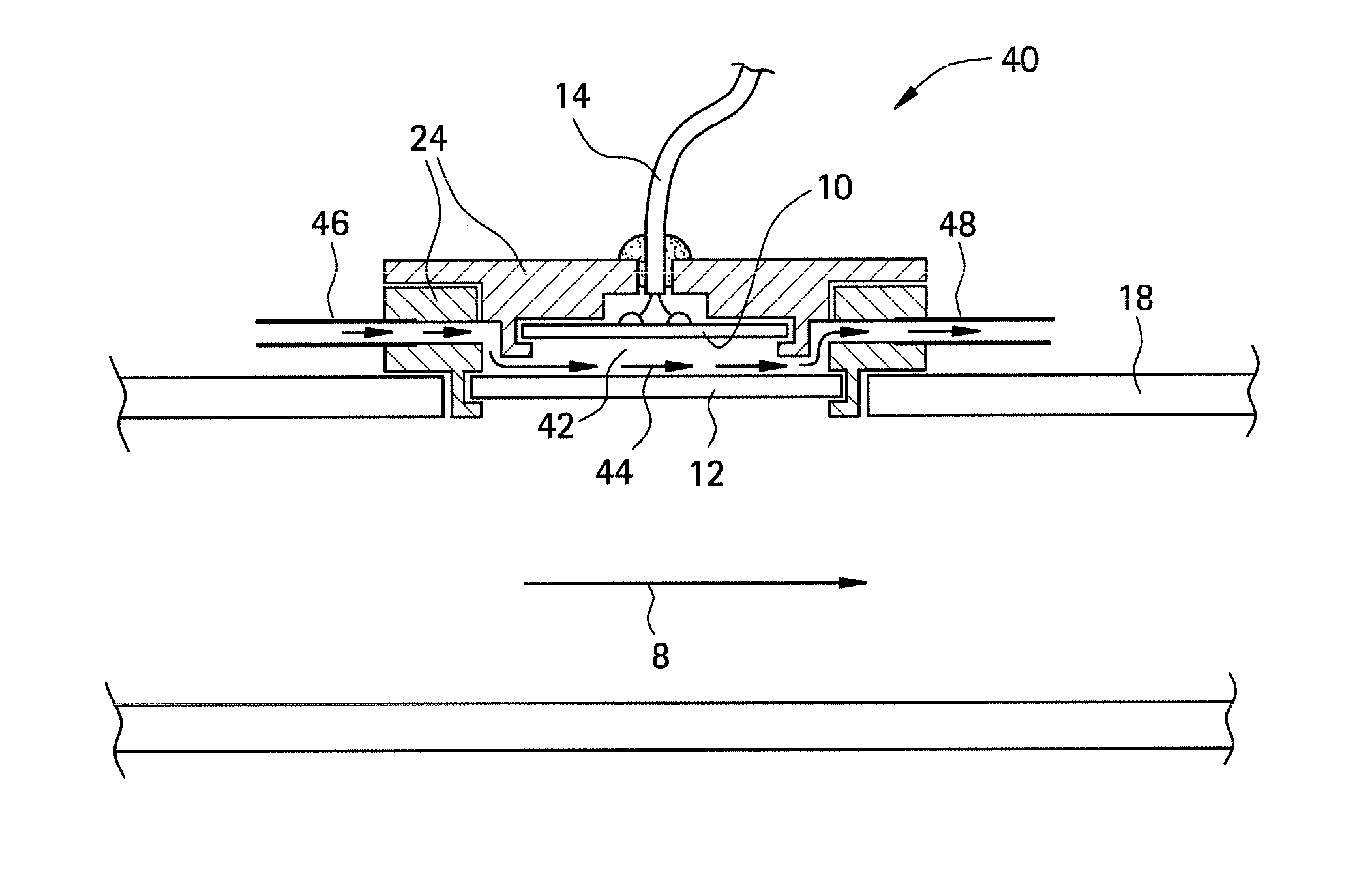
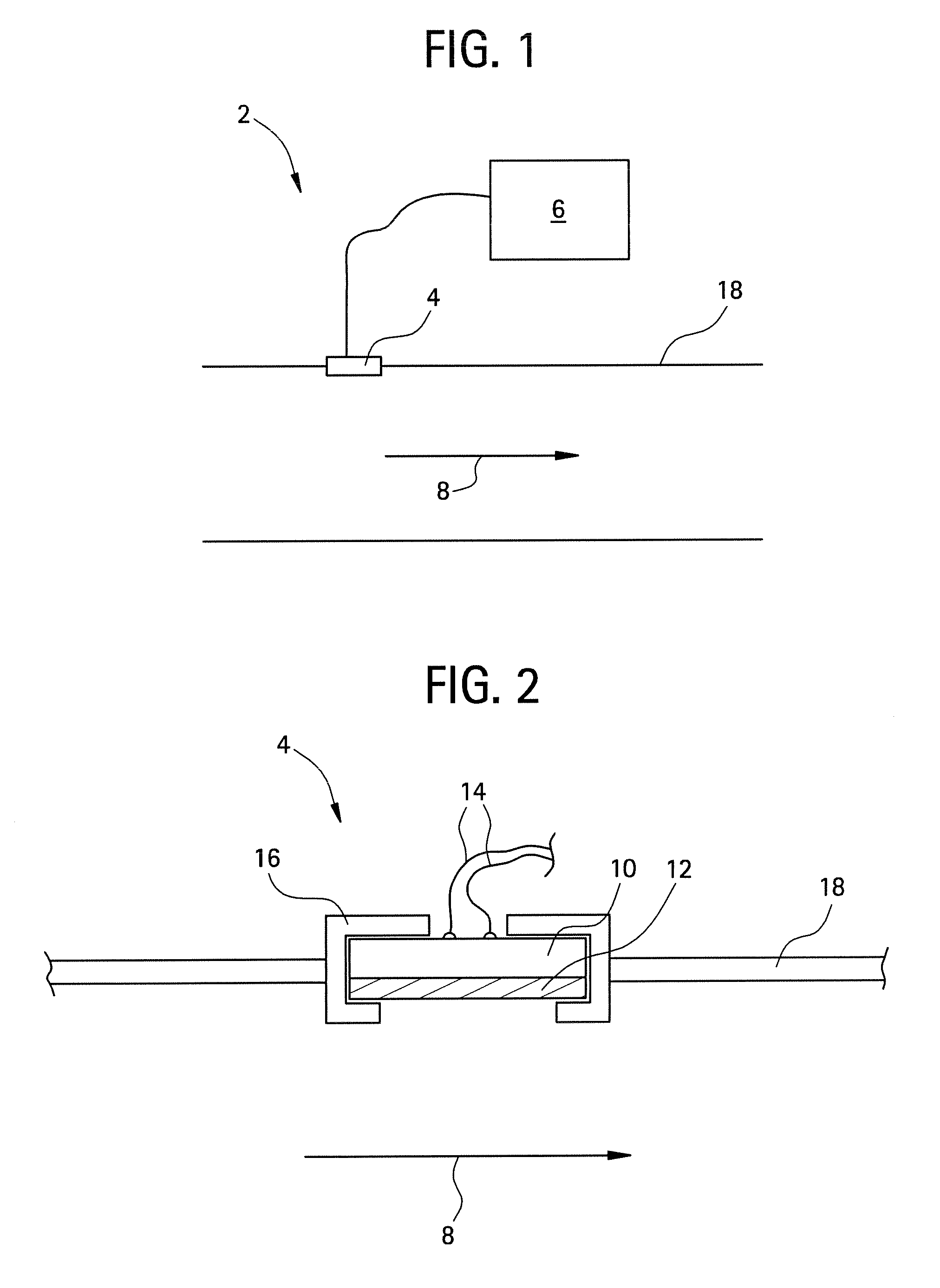
[0115]In the first experiment, a sensor 2 was constructed using a radio frequency identification tag as a transducer 10 (operating at nominal frequency of 13.56 MHz) and a polysulfone film 12. The RFID transducer was purchased from Digi-Key, under part number 481-1067-1-ND.

[0116]The sensor was assembled by dissolving polysulfone in dimethyl sulfoxide (DMSO, purchased from Aldrich Chemical Company Inc.) at 37° C. for 24 hours to produce a solution having about 10%-15% solids by volume. A coating was then applied to the RFID transducer and allowed to dry at 37° C. for 24 hours. After the coating was dry, the resulting film 12 had an average thickness of about 50 micrometers.

[0117]The polysulfone-coated sensor 2 was disposed within the conduit of a test apparatus. For comparison, an uncoated transducer 10 was also disposed within the conduit. A data acquisition system (LabVIEW, National Instruments, Inc) was operably connected to the sensor 2 and uncoated transducer 10 such that the Zm...

experiment 2

[0120]In a second experiment, a sensor 2 was constructed using a radio frequency identification tag as a transducer 10 (operating at nominal frequency of 13.56 MHz) and a poly(hydroxyethylmethacrylate) film 12. The sensor was assembled by dissolving poly(hydroxyethylmethacrylate) (Aldrich Chemical Co.) in 1-methoxy-2-propanol (Aldrich) at 20° C. for 24 hours to produce a solution having about 10%-15% solids by volume. A coating was then applied to the RFID transducer and allowed to dry at 20° C. for 24 hours. The resulting film 12 had an average thickness of about 10-50 micrometers.

[0121]The poly(hydroxyethylmethacrylate) coated sensor was disposed in a test apparatus similar to that utilized in Experiment 1 and Experiment 2, however an uncoated transducer was not employed. The apparatus was capable of measuring the Zmax of the poly(hydroxyethylmethacrylate) coated sensor 2 with respect to time.

[0122]The poly(hydroxyethylmethacrylate) coated sensor was subjected to a first aqueous s...

experiment 3

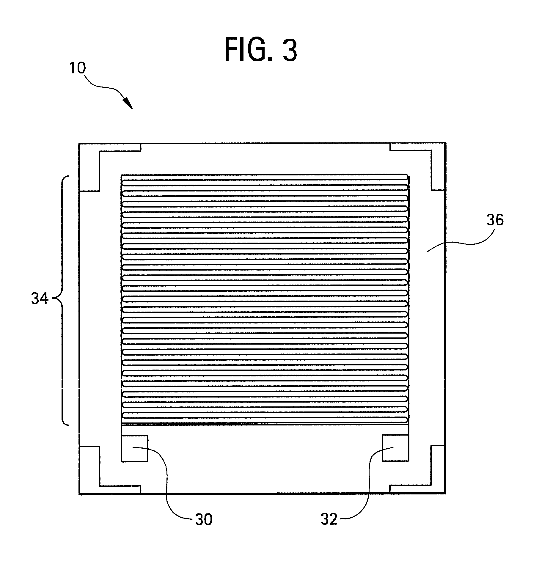
[0124]In a third experiment, a sensor 2 was constructed using a two-electrode gold interdigitated transducer 10 (see FIG. 3) and a polyaniline (PANI) film 12. The aniline monomer was purchased from Aldrich Chemical Company Inc., under part number 242284

[0125]The polymer film 12 was deposited by electropolymerizing the aniline monomer on the surface of the transducer at a concentration of 0.1 M aniline in 1 M H2SO4 under a cycling applied potential between −0.3 V and 1.1 V versus a silver / silver chloride reference at a rate of 50 mV per second. The resulting polyaniline film 12 had an average thickness of about 1 to about 100 micrometers.

[0126]The polyaniline coated sensor 4 was connected to a data acquisition system operated using LabVIEW, National Instruments and subjected to an aqueous solution comprising 40 ppb ZnCl. When the impedance appeared to plateau, water was introduced to purge the ions from the film 12. Thereafter a second aqueous solution comprising 190 ppb ZnCl was pas...


PUM

PropertyMeasurementUnit
thicknessaaaaaaaaaa
thicknessaaaaaaaaaa
thicknessaaaaaaaaaa

Abstract

In one embodiment, a method for detecting contaminants in a liquid comprises: contacting a sensor with a liquid, generating electrical information based upon a concentration of the contaminant in the liquid, transmitting the electrical information to a controller, and determining the concentration of a contaminant in the liquid. The sensor can comprise a film, a purge chamber, and a transducer, which are configured such that a first surface of the film is in fluid communication with the liquid and the purge chamber is in fluid communication with a second surface of the film that is opposite the first surface, and wherein the transducer is in fluid communication with the purge chamber.

Description

BACKGROUND[0001]Disclosed herein are apparatus and methods for detecting and quantifying contaminants in a liquid, and systems for use thereof.[0002]The detection of trace (e.g., less than 1% by volume) and microtrace (e.g., less than 1.0×10⁻⁶% by volume) levels of chemical contaminants in aqueous solutions is important for monitoring the condition of numerous applications. For example, ultrapure water (i.e. water having a microtrace concentration of ionic species) is desirable in many industrial processes including, but not limited to, the semiconductor, pharmaceutical, agricultural, chemical, energy, and food processing industries. In one specific example, nuclear reactors can employ ultrapure water for cooling purposes. The ultrapure water can comprise contaminants, which cause corrosion and other problems in the reactors fluid handling system. Therefore, a system and method for detecting and quantifying these contaminants is extremely desirable.[0003]The detection of chemical co...

Claims


Application Information

Patent Timeline
Patent Type & Authority Applications(United States)
IPC IPC(8): G01N27/06G01R27/02
CPCG21C17/022G21Y2002/204G21Y2002/303G01N33/1893G21Y2004/40G01N27/126G21Y2004/30Y02E30/30
Inventor POTYRAILO, RADISLAV ALEXANDROVICHMONK, DAVID JAMESTAMAKI, RYO
Owner GENERAL ELECTRIC CO
Why Eureka
Try Eureka