Phase Shifter with Photonic Band Gap Structure Using Ferroelectric Thin Film

a phase shifter and ferroelectric thin film technology, applied in waveguides, delay lines, electrical equipment, etc., can solve the problems of large insertion loss variation, many experiments to extract design parameters, etc., and achieve the effect of improving insertion loss and return loss characteristics, simple fabrication, and optimized structur

Inactive Publication Date: 2008-05-22
ELECTRONICS & TELECOMM RES INST
View PDF5 Cites 21 Cited by
  • Summary
  • Abstract
  • Description
  • Claims
  • Application Information

AI Technical Summary

Benefits of technology

[0013]The phase shifter of the present invention has an optimized combination of microstrip transmission line and tunable capacitors, thus providing improved insertion loss and return loss characteristics. The phase shifter implemented with microstrips is very simple to fabricate and is usable over a wide range of frequencies due to its wide band characteristics. The phase shifter also has an optimized structure including the IDT tunable capacitors and the PBGs, thus providing low microwave loss.

Problems solved by technology

However, typical phase shifters require many experiments to extract design parameters.
Another drawback of phase shifters is that they suffer from large insertion loss variation because characteristic impedance and phase shift vary according to an applied voltage.

Method used


Image

  • Phase Shifter with Photonic Band Gap Structure Using Ferroelectric Thin Film
  • Phase Shifter with Photonic Band Gap Structure Using Ferroelectric Thin Film
  • Phase Shifter with Photonic Band Gap Structure Using Ferroelectric Thin Film

Examples


Embodiment Construction

[0026]The present invention will now be described more fully with reference to the accompanying drawings, in which exemplary embodiments of the invention are shown.

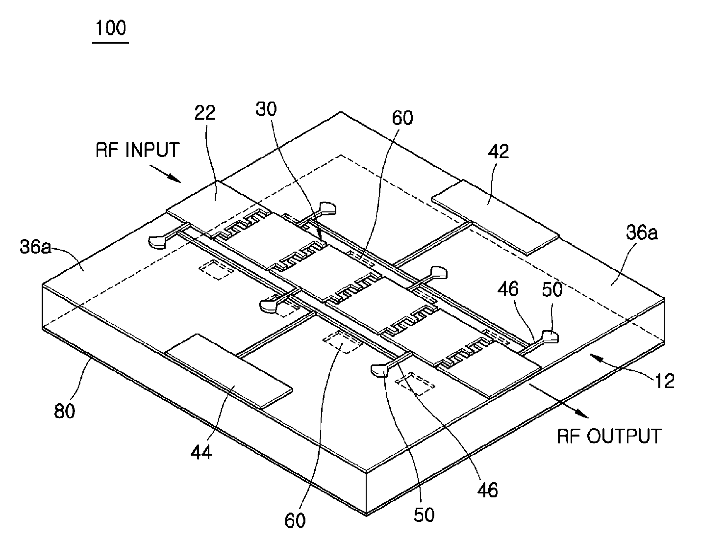
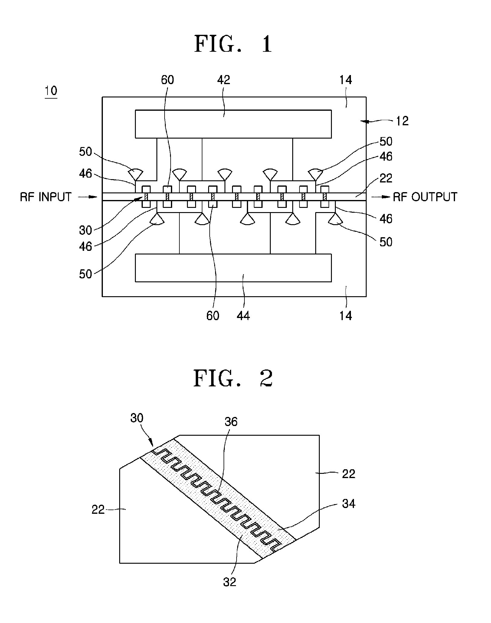
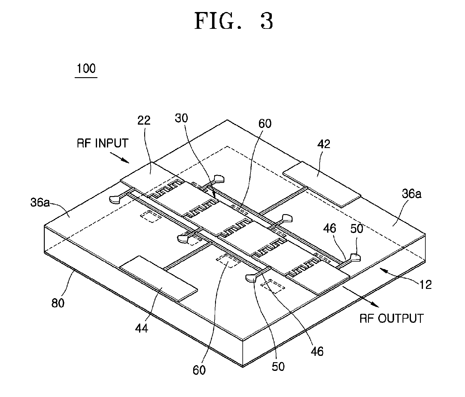
[0027]FIG. 1 is a plan view of an analog phase shifter 10 according to a preferred embodiment of the present invention. Referring to FIG. 1, the analog phase shifter 10 includes a microstrip transmission line 22 mounted on a substrate 12. The microstrip transmission line 22 acts as a microwave input / output line. The substrate 12 may be comprised of an oxide single crystal substrate formed of, for example, Mgb, LaAlO3, or Al2O3, a ceramic or high-resistive Si semiconductor substrate, a glass substrate, or a semi-insulating gallium arsenide substrate.

[0028]A plurality of tunable capacitors 30 are embedded in the microstrip transmission line 22. FIG. 2 is an enlarged view illustrating the detailed configuration of each tunable capacitor 30. The tunable capacitor 30 has an IDT pattern with a ferroelectric thin film 36 between...


PUM


Abstract

Provided are a phase shifter with a photonic band gap (PBG) structure using a ferroelectric thin film. The phase shifter includes a microstrip transmission line acting as a microwave input/output line and a plurality of tunable capacitors arranged in the microstrip transmission line at regular intervals. Electrodes disposed on a substrate apply DC voltages to the plurality of tunable capacitors. Radio frequency (RF) chokes and quarter wavelength radial-stubs are connected between the electrodes and the microstrip transmission line in order to prevent high frequency signals from flowing into a DC bias terminal. A plurality of PBGS are periodically arrayed on a ground plane of the substrate.

Description

CROSS-REFERENCE TO RELATED PATENT APPLICATION[0001]This application claims the benefit of Korean Patent Application No. 10-2004-0108981, filed on Dec. 20, 2004, in the Korean Intellectual Property Office, the disclosure of which is incorporated herein in its entirety by reference.BACKGROUND OF THE INVENTION[0002]1. Field of the Invention[0003]The present invention relates to a microwave tunable device, and more particularly, to a tunable capacitor using a ferroelectric thin film and a phase shifter using a photonic band gap (PBG) structure.[0004]2. Description of the Related Art[0005]PBG structures were first introduced in the field of optics, but have recently been widely used in high frequency devices such as radio frequency (RF) and microwave devices.[0006]Phase shifters are widely used in microwave systems to steer electron beams and shift the frequency of a radio signal. A phase shifter is an essential component of a phase array antenna system for producing a beam pattern and s...

Claims


Application Information

Patent Timeline
Patent Type & Authority Applications(United States)
IPC IPC(8): H01P1/18
CPCH01P1/2005H01P1/181H01P1/18
Inventor KIM, YOUNG-TAERYU, HAN-CHEOLKWAK, MIN-HWANMOON, SEUNG-EONLEE, SU-JAEKANG, KWANG-YONG
Owner ELECTRONICS & TELECOMM RES INST
Why Eureka
Try Eureka