

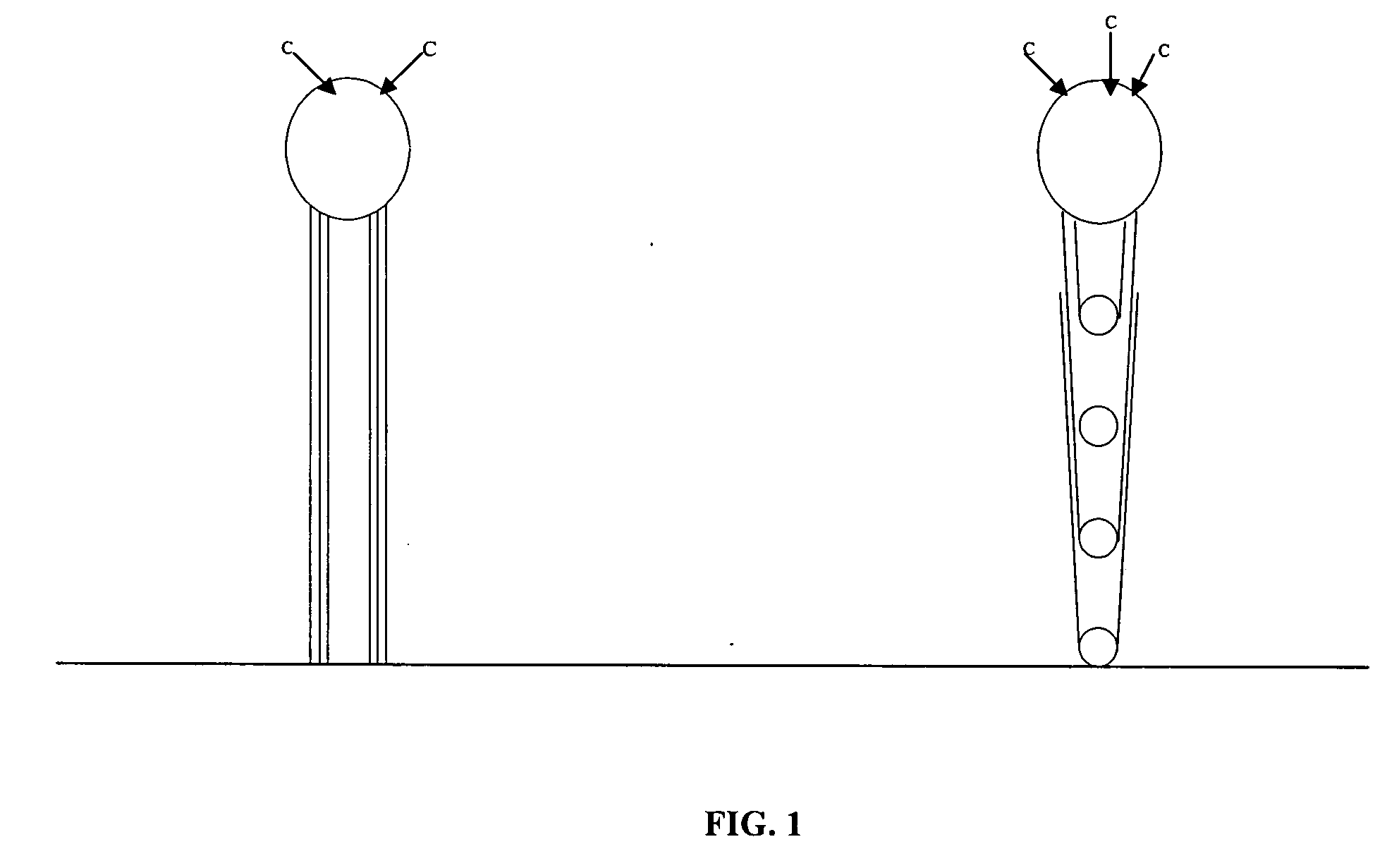
Varied morphology carbon nanotubes
a carbon nanotube and morphology technology, applied in the field of varied morphology carbon nanotubes, can solve the problems of large quantity, cost-effective production methods, and only providing a uniform flat surface, and achieve the effects of increasing the yield of cnt products, promoting the activity of catalytic substrates, and rapid carbon deposition and cnt growth
- Summary
- Abstract
- Description
- Claims
- Application Information
AI Technical Summary
Benefits of technology
Problems solved by technology
Method used
Image

Examples
example 1
Preparation of Catalyst Substrate for Synthesis of Linear CNTs
[0058]Mesoporous silica containing iron nanoparticles were prepared by a sol-gel process by hydrolysis of tetraethoxysilane (TEOS) in the presence of iron nitrate in aqueous solution following the method described by Li et al. (Science, (1996), Vol. 274, 1701-3) with the following modification. The catalyst gel was dried to remove excess water and solvents and calcined for 10 hours at 450° C. and 10−2 torr to give a silica network with substantially uniform pores containing iron oxide nanoparticles that are distributed within. The catalyst gel is then ground into a fine, micro-particulate powder either mechanically using a ball mill or manually with a pestle and mortar. The ground catalyst particles provide particle sizes that range between 0.1 and 100 μM under the grinding conditions.
example 2
Preparation of Catalyst Substrate for Synthesis of Branched CNTs
[0059]Magnesium oxide (MgO) supported cobalt (Co) catalysts were prepared by dissolving 0.246 g of cobalt nitrate hexahydrate (Co(NO3)2.6H2O, 98%) in 40 ml ethyl alcohol, following which immersing 2 g of particulate MgO powder (−325 mesh) were added to the solution with sonication for 50 minutes. The solid residue was filtered, dried and calcined at 130° C. for 14 hours.
example 3
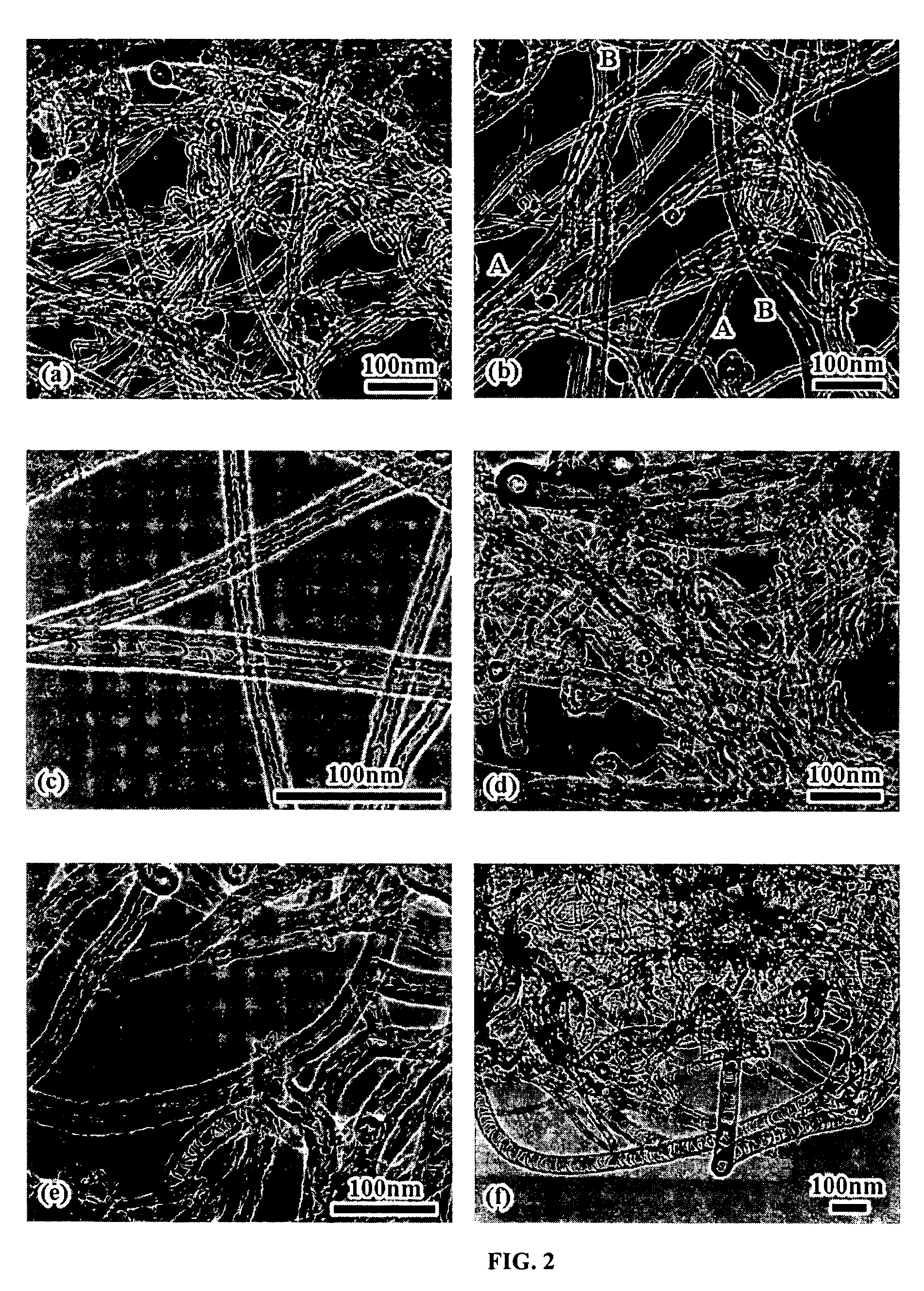
General Synthetic Procedure for Linear CNTs
[0060]The synthesis of CNTs is carried out in a quartz tube reactor of a chemical vapor deposition (CVD) apparatus. For each synthetic run, 100 mg of the micro-particulate catalyst substrate was spread onto a molybdenum boat (40×100 mm2) either mechanically with a spreader or by spraying. The reactor chamber was then evacuated to 10−2 torr, following which the temperature of the chamber was raised to 750° C. Gaseous ammonia was introduced into the chamber at a flow rate of 80 sccm and maintained for 10 minutes, following which acetylene at a flow rate of 20 sccm was introduced for initiate CNT growth. The total gas pressure within the reaction chamber was maintained at a fixed value that ranged from 0.6 torr to 760 torr (depending on desired morphology for the CNTs). The reaction time was maintained constant at 2 hours for each run. The catalytic substrate containing attached CNTs were washed with hydrofluoric acid, dried and weighed prior ...
PUM
| Property | Measurement | Unit |
|---|---|---|
| angle | aaaaa | aaaaa |
| angle | aaaaa | aaaaa |
| temperature | aaaaa | aaaaa |
Abstract
Description
Claims
Application Information