Particle separation and concentration system

a technology applied in the field of particle separation and concentration system, can solve the problems of increasing the complexity of the device, particular field method, and the growth of most of the techniques, and achieve the effect of reducing the radius of curvatur

Active Publication Date: 2008-06-05
XEROX CORP
View PDF89 Cites 124 Cited by
  • Summary
  • Abstract
  • Description
  • Claims
  • Application Information

AI Technical Summary

Benefits of technology

[0013]In another aspect of the presently described embodiments, the radius of curvature decreases along the channel.

Problems solved by technology

Most of these techniques have seen exponential growth but are batch processes that require set-up time for each sample lot.
Though the FFF technique is versatile and has the potential to be miniaturized, the requirement of an external field may increase the complexity of the device.
Also, the use of a particular field method might limit its area of application to certain reagents (e.g. Magnetic FFF).
Difficulties with these types of implementations have been experienced, however.
For example, all of these approaches require an additional external force, are limited to batch processing and are scaled only to handle small volumes of a sample.
In particular, the Tri-Service Standard for anthrax spores is 100 cfus / L, which poses a significant challenge in logistics, time, and concentration factor.
The biggest challenge to this method and to all these vendors is the low yield and laborious back-flush recovery of captured pathogens from these membranes.

Method used


Image

  • Particle separation and concentration system
  • Particle separation and concentration system
  • Particle separation and concentration system

Examples


Embodiment Construction

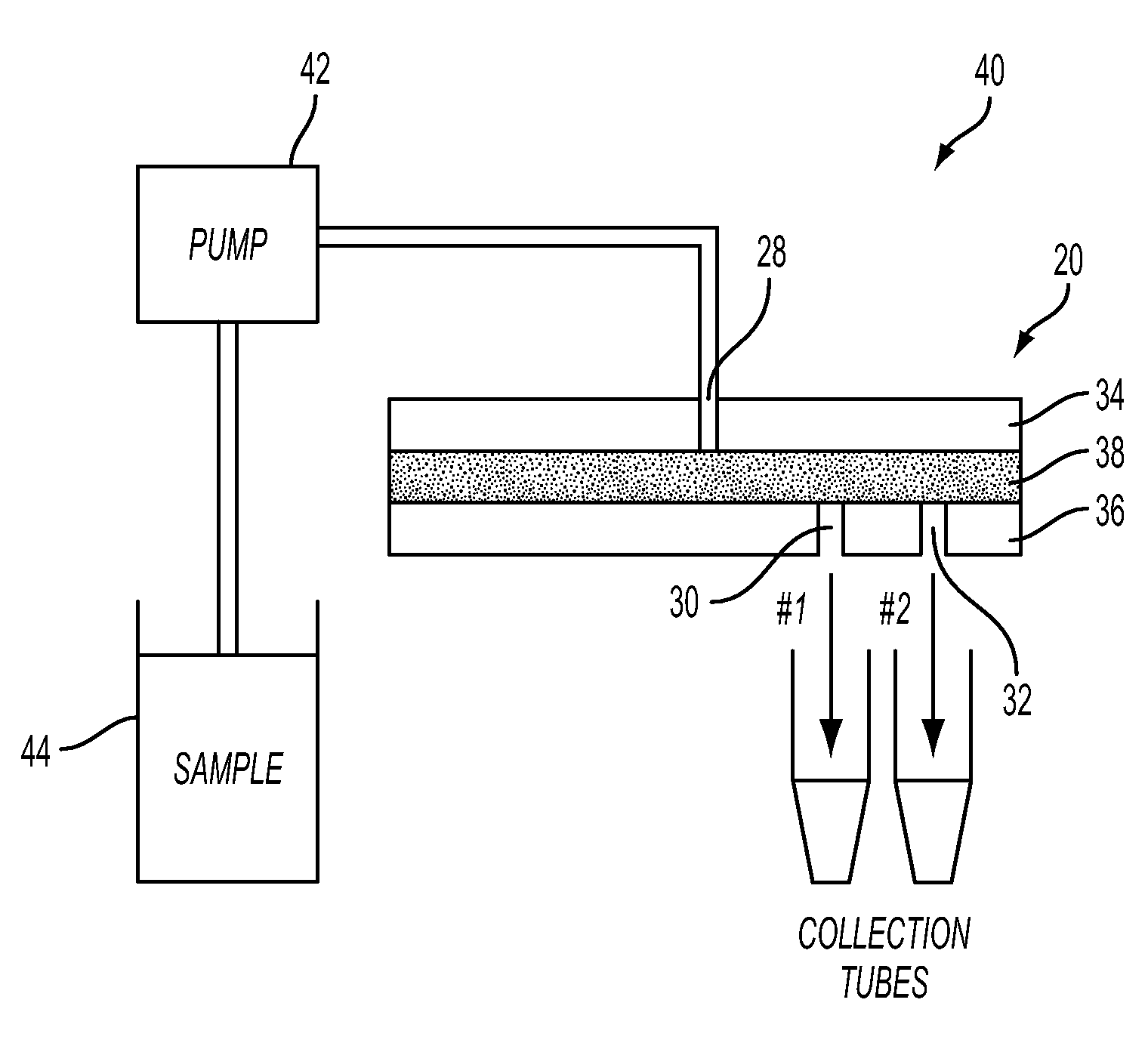
[0047]Systems according to the presently described embodiments utilize channel geometry and velocity to exert the required force to separate particles to outside or inside channel walls. These embodiments may span micro-scale to macro-scale fluid capacities. Thus, many forms are possible, allowing parallelization or extended channel lengths through helical stacking of planar structures. As an additional advantage, materials and fabrication cost are also very low, thus allowing for disposable use.

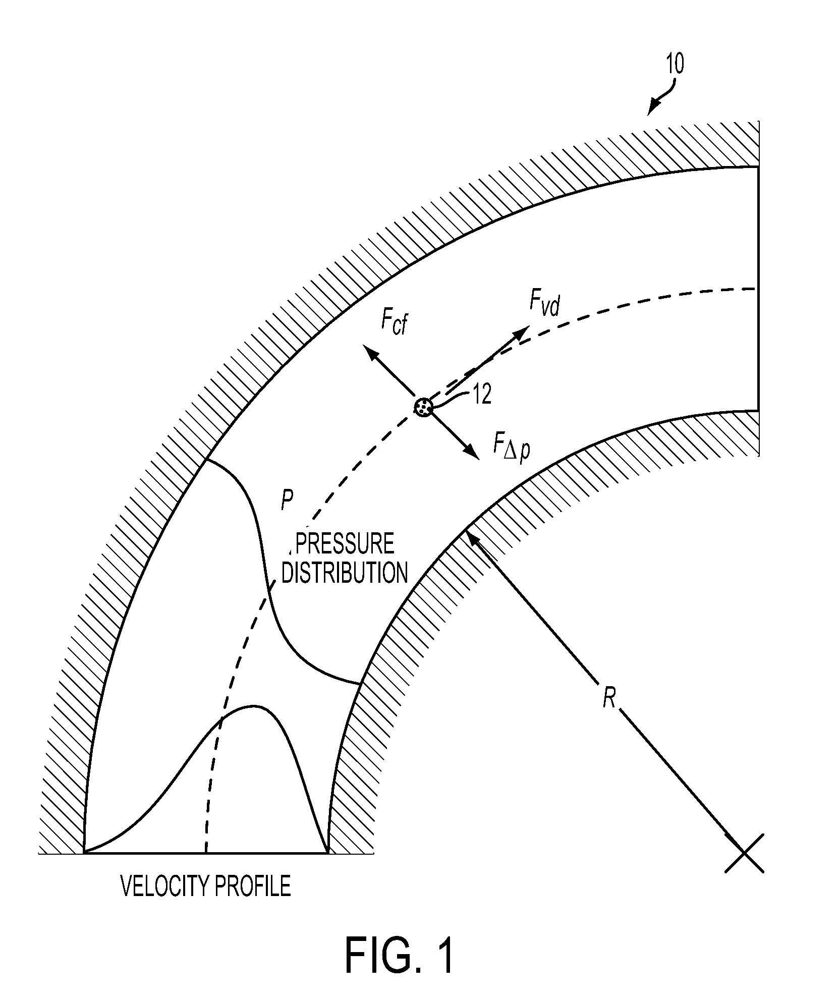
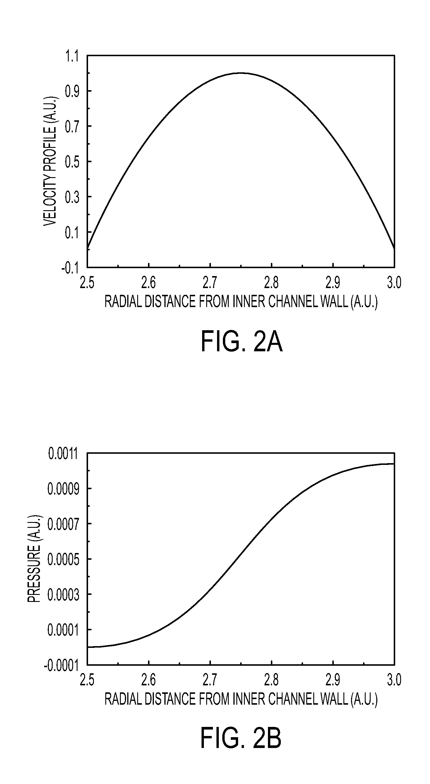
[0048]With reference to FIG. 1, a segment of a curved channel 10 showing various forces acting on a particle 12. Also, the velocity profile and the pressure distribution is shown.

[0049]Analytic consideration for the flow in a curved channel is as follows. In this regard:

[0050]V=Flow velocity

[0051]p=Pressure

[0052]Fcf=Centrifugal force on the particle

[0053]FΔp=Force due to pressure differential

[0054]Fvd=Force due to viscous drag

[0055]R=Radius of curvature of the channel

[0056]η=Dynamic viscosit...


PUM

PropertyMeasurementUnit
semicircular radiusaaaaaaaaaa
sizeaaaaaaaaaa

Abstract

This invention is based on size and mass separation of suspended particles, including biological matter, which are made to flow in a spiral channel. On the spiral sections, the inward directed transverse pressure field from fluid shear competes with the outward directed centrifugal force to allow for separation of particles. At high velocity, centrifugal force dominates and particles move outward. At low velocities, transverse pressure dominates and the particles move inward. The magnitudes of the two opposing forces depend on flow velocity, particle size, radius of curvature of the spiral section, channel dimensions, and viscosity of the fluid. At the end of the spiral channel, a parallel array of outlets collects separated particles. For any particle size, the required channel dimension is determined by estimating the transit time to reach the side-wall. This time is a function of flow velocity, channel width, viscosity, and radius of curvature. Larger particles may reach the channel wall earlier than the smaller particles which need more time to reach the side wall. Thus a spiral channel may be envisioned by placing multiple outlets along the channel. This technique is inherently scalable over a large size range from sub-millimeter down to 1 μm.

Description

BACKGROUND[0001]Particle separation and sorting are functions necessary in many biological and chemical processes for both macro-scale and miniaturized lab-on-chip applications. Some of the methods employed today are mechanical sieving and sedimentation—which are usually reserved for separation of large particles. Large scale water purification and mining / mineral recovery applications require large volume, high throughput, and rapid processing capabilities. Current water purification methods require sand beds and even membrane filters depending on the desired water quality. For example, mineral processing uses a spiral concentrator design where a helical trough allows heavy minerals to sediment near the center while centrifugal force pushes lighter particles outward where they are transported away. The tray has a sloped cross-section which is deeper near the axis of the helix.[0002]Techniques such as hydrodynamic chromatography, size exclusion chromatography and electrophoresis allo...

Claims


Application Information

Patent Timeline
Patent Type & Authority Applications(United States)
IPC IPC(8): B03B5/00
CPCB01D2311/04B01D2311/16B01D2321/2025B03B5/32B04C1/00B01D2221/10G01N15/04G01N15/0255B01D21/265B01D2311/2676B01L3/502761B01L3/502776
Inventor LEAN, MENG H.SEO, JEONGGIKOLE, ASHUTOSHCHANG, NORINE E.HO LIMB, SCOTT JONG
Owner XEROX CORP
Why Eureka
Try Eureka