Nanocomposite coatings for threaded connections

a nanocomposite coating and threaded connection technology, applied in the direction of synthetic resin layered products, drilling pipes, pipe elements, etc., can solve the problems of slipping contact between the threads and other surfaces of the pipes, significant drawbacks of dope, environmental hazards,

Active Publication Date: 2008-06-05
TENARIS CONNECTIONS
View PDF99 Cites 67 Cited by
  • Summary
  • Abstract
  • Description
  • Claims
  • Application Information

AI Technical Summary

Benefits of technology

[0052]where the balance of the first coating composition is comprised of the epoxy and where the pe

Problems solved by technology

During assembly of either of the casing or tubing pipes, galling in the threads and other surfaces of the pipes which are in sliding contact is a significant problem which may arise.
The use of dope presents significant drawbacks, however.
Notably, excessive concentrations of heavy metals can result in their accumulation in the bodies of humans and animals, causing serious illness.
Furthermore, the heavy metals present in dope may possibly contaminate soil, groundwater, and ocean water, presenting an environmental hazard.
Furthermore, in light of these hazards, strict regulations prohibiting discharge of heavy metals requires precautions when utilizing dope that increases the cost of its use.
In addition to the aforementioned issues, the use of dope necessitates other operations, such as cleaning and doping of the threaded connections in the field during use.
These operations are expensive and time consuming, however, as they are labor intensive.
Additionally, these operations expose personnel to safety risks, as they require exposure to moving pipes and often take place under adverse conditions.
Another potential risk in the use of dope is the danger of either “underdoping” or “overdoping.” In underdoping, insufficient dope is provided and/or the dope fails to distribute over the entire surface of the threaded connection, resulting in a failure

Method used


Image

  • Nanocomposite coatings for threaded connections
  • Nanocomposite coatings for threaded connections
  • Nanocomposite coatings for threaded connections

Examples


example 1

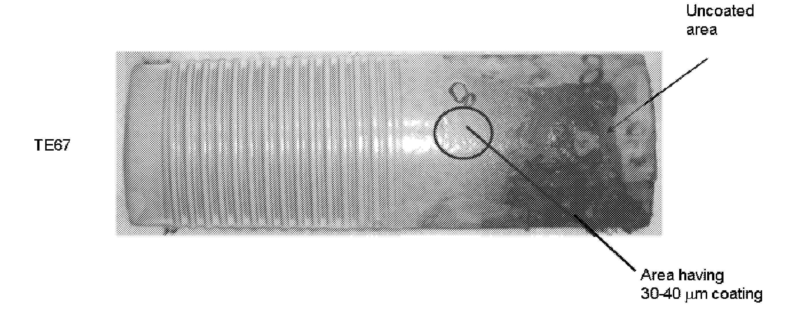
Cross-Cut Tape Tests

Graphite / Polyimide Compositions

[0141]The cross-cut tape test was used to characterize the adhesion of the coating according to ASTM D3359-02, “Standard Test Methods for Measuring Adhesion by Tape Test”. According to the standard, a bladed cutting tool is used to make the cross-hatch cuts in the coating deposited on the substrate. Subsequently, an adhesive tape is placed over the cut surface and then peeled off. If parts of the coating remain on the tape, the coating's adhesion is determined to be insufficient.

[0142]The classification of test results is done by a visual comparison with the Standard, which defines the affected area of the test section in terms of the percentage of the coating which is detached from the surface by the pull-off tape. A rating of 0 through 5 classifies the adhesion of the test sample section from 100% pass (0) to fail (5), where more than 65% of the test area delaminates from the surface.

[0143]The Cross Cut Tape Test showed good adhes...

example 2

Tribological Characterization

Graphite / Polyimide Nanocomposites

[0144]The influence of the solid state lubricants and the reinforcement on the friction and wear of the nanocomposite was examined through pin-on-disc tribometer testing according to DIN 50324. Approximate testing parameters comprised P=2 N, v=10 cm / s, 10 cm / s, r=15 mm, and s=1000 m. Coating systems TP9, TP13, TP14, and TP15 were investigated, each having approximately equal amounts of D10H, about 1.5 g. Notably, the TP9 sample lacks the SiC reinforcement.

[0145]The results of the pin-on-disc testing are presented in FIG. 5 and summarized in Table 1 above, where k is the wear resistance. From FIG. 5 it can be derived that, with graphite as solid state lubricant, coefficients of friction in the ranged of μ=0.1-0.2 were obtained. The measured wear coefficients were found to be around k=2.5*10−4 mm3 / Nm. The low wear resistance for graphite containing coatings is believed to be caused by the intrinsic softness of graphite, whi...

example 3

Surface Roughness

Graphite / Polyimide Coating Systems

[0146]An important tribology topic is the question of how the surface roughness influences the friction behavior. As friction and wear are generally concurrent processes, wear debris generally starts developing from the point when a sliding process occurs on a surface. These debris increase the friction coefficient dramatically and, therefore, it is important that they are removed away from the sliding path. This removal is done by the collection of the debris in the depressions of the surface roughness. Since wear depends also on the surface roughness, with rough surfaces producing more wear debris than smooth surfaces, there may be determined a range of surface roughness which substantially optimizes the wear / friction balance. This effect can be seen in the surface with the lowest friction coefficient.

[0147]In the polyimide system, the surface roughness is modified and substantially optimized by using the polymeric carbon fluorina...


PUM

PropertyMeasurementUnit
Temperatureaaaaaaaaaa
Lengthaaaaaaaaaa
Timeaaaaaaaaaa

Abstract

Coating systems which provide corrosion resistance and, optionally, lubrication, for threaded connections are disclosed. The compositions comprise a first coating composition comprising polymer matrices of polyimides or epoxies which are modified with small amounts of a fluorine containing polymer. Also present in the coating compositions are corrosion inhibiting agents and inorganic particles having a mean diameter of between approximately 10 nm and 10 μm. Solid lubricants, which may include at least one of PTFE, HDPE, Graphite, and MoS2, are optionally added to provide the first coating with a low coefficient of friction. The coating systems may further comprise a second coating composition, comprising a solid lubricant dispersed within an epoxy resin and a solvent. The first and second coating compositions are deposited on at least a portion of at least one of the pin and box members of the threaded connections.

Description

CROSS REFERENCE TO RELATED APPLICATIONS[0001]This application claims the benefit of priority under 35 U.S.C. §119(e) of U.S. Provisional Application No. 60 / 872,615, filed on Dec. 1, 2006, entitled Nanocomposite Coatings for Lubrication and Corrosion Resistance, U.S. Provisional Application No. 60 / 914,699, filed Apr. 27, 2007, entitled Polymer Coating for Lubricating and Corrosion Resistance, and U.S. Provisional Patent Application No. 60 / 940,690, filed May 29, 2007, entitled Coatings for Lubrication and Corrosion Resistance, the entirety of each of which is incorporated herein by reference.BACKGROUND OF THE INVENTION[0002]1. Field of the Invention[0003]Embodiments of the invention relate to coating systems, particularly for threaded connections, and, in one embodiment, to nanocomposite coatings for corrosion resistance.[0004]2. Description of the Related Art[0005]In oilfields, it is common practice to use metallic pipes to extract oil or gas from underground reservoirs or pools. Thi...

Claims


Application Information

Patent Timeline
IPC IPC(8): F16L58/04
CPCC09D163/00Y10T428/263E21B17/042F16L58/1027F16L58/182C09D179/08Y10T428/269Y10T428/2495Y10T428/257Y10T428/24355Y10T428/24967C08K3/22C08K3/24C08K3/34C08L27/18C09D5/08C09D127/18Y10T428/24587F16L58/1072C10M2201/041C10M2201/062C10M2201/066C10M2201/085C10M2205/022C10M2213/062C10M2229/041C10N2210/02C10N2230/06C10N2230/12C10N2250/18Y10T428/259Y10T428/24975Y10T428/25Y10T428/256Y10T428/26C08L27/00C08L2666/04C08L2666/14Y10T428/31544Y10T428/31725Y10T428/3154Y10T428/31511C10N2010/04C10N2030/06C10N2030/12C10N2050/14
Inventor CARCAGNO, GABRIEL EDUARDOENDRES, KLAUS
Owner TENARIS CONNECTIONS
Why Eureka
Try Eureka