Ceramics composite member and method of producing the same

a composite member and ceramic technology, applied in the field of ceramic composite members, can solve the problems of limited heat resistance and strength of parts, limited application shape of components, limited sintering of silicon carbide, etc., and achieve the effects of good reproducibility, enhanced strength, and mechanical properties

Inactive Publication Date: 2008-06-05
KK TOSHIBA
View PDF4 Cites 43 Cited by
  • Summary
  • Abstract
  • Description
  • Claims
  • Application Information

AI Technical Summary

Benefits of technology

[0012]According to an aspect of the present invention, there are provided a ceramics composite member with mechanical properties such as strength enhanced with a good reproducibility by making a bonding layer homogeneous and minute, and a method of producing the same.

Problems solved by technology

But, such bonding methods have a disadvantage that the heat resistance and strength of the parts are limited depending on a metal layer which is present as a bonding layer.
But, the conventional bonding method using the reaction sintering of silicon carbide has a disadvantage that applicable component shapes are limited because the melted silicon impregnates through the pores in the porous body of silicon carbide.
It also has a disadvantage that the strength of the bonded body cannot be enhanced sufficiently because the process of producing the silicon carbide in the bonding layer cannot be controlled.
They are causes to degrade the strength of the bonded body.
But, the generation of the silicon carbide particles configuring the bonding layer based on only the carbon in the organic adhesive has a drawback that it is poor in reproducibility of bonding strength.
Therefore, the interstices of the silicon carbide particles tend to become heterogeneous, and there is a possibility that the free silicon phase segregates.
Thus, it is a cause of lowering of the reproducibility of the bonding strength of a bonded part applying the bonding method using the organic adhesive.

Method used


Image

  • Ceramics composite member and method of producing the same
  • Ceramics composite member and method of producing the same
  • Ceramics composite member and method of producing the same

Examples


example 1

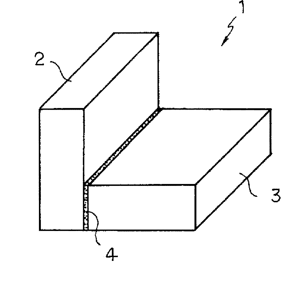
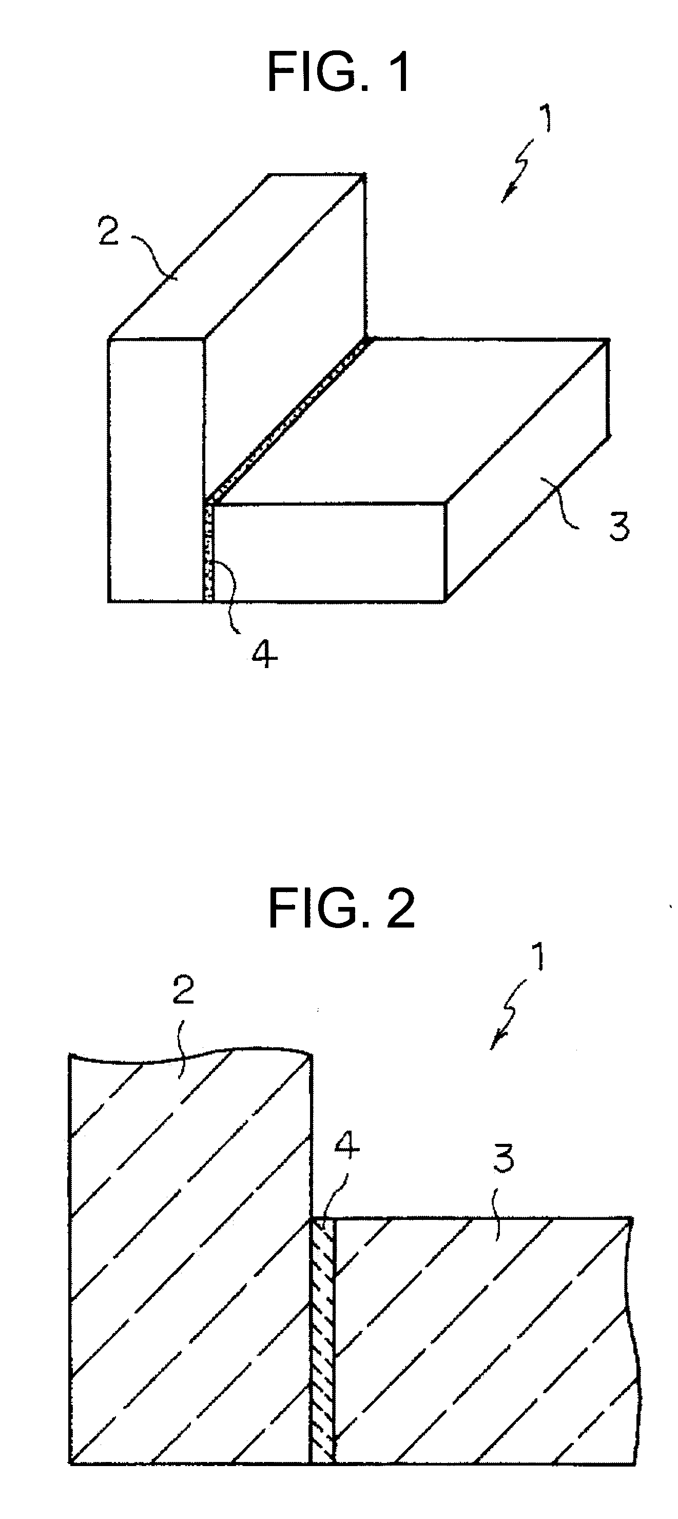
[0069]Silicon carbide powder having an average particle diameter of 0.5 μm and carbon powder (carbon black) having an average particle diameter of 0.01 μm were mixed at a mass ratio of 10:3 (=SiC:C). The mixture powder was mixed with an appropriate amount of an organic binder, and the mixture was dispersed into a solvent to prepare a slurry. The slurry was charged into a forming die under a pressure of 1 MPa by a pressure casting machine. Thus, two plate-like shaped bodies having a prescribed shaped body density were produced.

[0070]Then, the two plate-like shaped bodies were air dried and adhered with an adhesive. As the adhesive, a mixture of a phenol resin with silicon carbide powder having an average particle diameter of 0.1 μm and carbon powder (carbon black) having an average particle diameter of 0.08 μm was used. The ratio between the silicon carbide powder and the carbon component derived from the carbon powder and the phenol resin was determined to be SiC:C=25:75. The adhere...

example 2

[0072]Two shaped bodies produced in the same manner as in Example 1 described above were heated and kept at a temperature of 600° C. in an inert gas atmosphere to remove (degrease) the organic binder. The degreased shaped bodies were heated to a temperature of 1400° C. or more under reduced pressure or in an inert gas atmosphere, and the shaped bodies kept in the heated state were impregnated with melted silicon. In the melted silicon impregnation step, the shaped bodies were subjected to reaction-sintering to obtain two Si—SiC composite sintered bodies.

[0073]Then, the adhered surfaces of the two SiC radical reaction sintered bodies were subjected to a blast treatment and adhered with an adhesive. As the adhesive, a mixture of a phenol resin with silicon carbide powder having an average particle diameter of 1 μm and carbon powder (carbon black) having an average particle diameter of 0.8 μm was used. The ratio between the silicon carbide powder and the carbon component derived from t...

examples 3 to 10

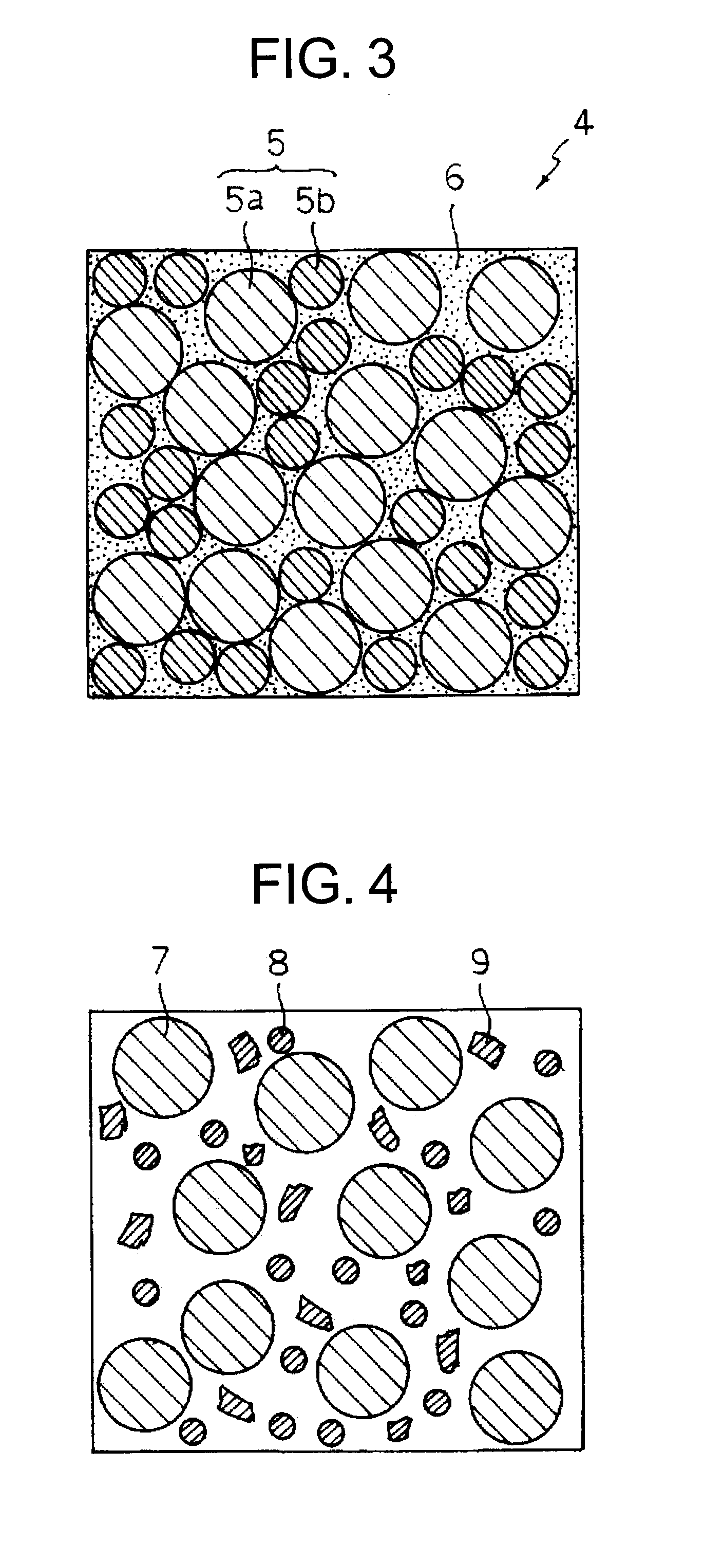
[0075]As to-be-bonded members, an Si—SiC composite sintered body, shaped bodies for Si—SiC composite body, an ordinary SiC sintered body, an Si3N4 sintered body, a ZrO2 sintered body and an SiC-continuous fiber composite material were prepared. They were coupled according to the combinations shown in Table 1 to produce ceramics composite members. The coupling step was performed in the same manner as in Examples 1 and 2. The adhesives used for coupling had the compositions as shown in Table 1. Table 1 also shows the properties of the joint portions. The joint portions of the ceramics composite members had the texture in which the free Si phase is continuously provided in the network form in the interstices of the SiC particles, and also had the single layer structure. The individual ceramics composite members were subjected to the characteristic evaluation to be described later.


PUM

PropertyMeasurementUnit
diameteraaaaaaaaaa
diameteraaaaaaaaaa
particle diameteraaaaaaaaaa

Abstract

A ceramics composite member includes a structure in which a first ceramic member and a second ceramic member are integrated with a joint portion. The joint portion has a texture in which a silicon phase having an average diameter of 0.05 μm or more and 10 μm or less is continuously provided in a network form in interstices of silicon carbide particles having an average particle diameter of 0.1 μm or more and 0.1 mm or less.

Description

CROSS-REFERENCE TO RELATED APPLICATIONS[0001]This application is based upon and claims the benefit of priority from the prior Japanese Patent Application No. 2006-324306 filed on Nov. 30, 2006; the entire contents of which are incorporated herein by reference.BACKGROUND OF THE INVENTION[0002]1. Field of the Invention[0003]The present invention relates to a ceramics composite member and method of producing the same.[0004]2. Description of the Related Art[0005]Structural ceramics are used as heat-resistant members and abrasion-resistant members because they excel in environment resistance, heat resistance and abrasion resistance and also have outstanding characteristics such as high rigidity, low thermal expansion and low specific gravity. Ceramic members such as alumina (Al2O3), zirconia (ZrO2), silicon nitride (Si3N4) and silicon carbide (SiC) are being worked mainly toward practical use for semiconductor-related components such as jigs for semiconductor production equipment and oth...

Claims


Application Information

Patent Timeline
Patent Type & Authority Applications(United States)
IPC IPC(8): B32B18/00C03B29/00
CPCB82Y30/00Y10T428/24421C04B37/005C04B37/006C04B37/008C04B2235/3826C04B2235/422C04B2235/424C04B2235/48C04B2235/5427C04B2235/5436C04B2235/5445C04B2235/5454C04B2235/77C04B2235/96C04B2235/9607C04B2237/16C04B2237/348C04B2237/363C04B2237/365C04B2237/368C04B2237/38C04B2237/62C04B2237/708C04B35/573
Inventor SUYAMA, SHOKOITO, YOSHIYASUMARUYAMA, SHIGEKIHANDA, NORIHIKO
Owner KK TOSHIBA
Why Eureka
Try Eureka