Apparatus and method for inductive heating a workpiece using an interposed thermal insulating layer

a technology of thermal insulation layer and workpiece, which is applied in the direction of electric/magnetic/electromagnetic heating, dough shaping, manufacturing tools, etc., can solve the problems of slow control response of oil's thermal mass, limited application of oil-heated devices, and ineffective cost-effectiveness, so as to reduce resistive losses, increase heating efficiency, and reduce electrical resistance

Inactive Publication Date: 2008-06-12
COMAINTEL +1
View PDF28 Cites 44 Cited by
  • Summary
  • Abstract
  • Description
  • Claims
  • Application Information

AI Technical Summary

Benefits of technology

[0027]By interposing a thermal insulating layer between the induction coils and the heated workpiece, heat generated within the workpiece cannot substantially escape through the insulation to the environment. This raises the heating efficiency and protects the external induction windings from elevated temperatures. Maintaining the induction coil's windings at lower temperatures reduces their electrical resistance to further reduce resistive losses, which in turn increases the system's overall energy efficiency.
[0028]Another unique characteristic of induction heating using a helical tunnel coil in this invention is that the distribution of transferred energy along the length of the workpiece is inversely proportional to the pitch of the helix. By varying the pitch of the windings additional embodiments of the present invention are envisioned that can profile the heat generation along the length of an enclosed workpiece, in an intentionally non-uniform, predictable manner to complement and optimize transition of the processed material from solid to molten phases. In other words, with extruder and molding applications this invention allows the distrib

Problems solved by technology

Due to the added cost and complexity, and the slower control response of the oil's thermal mass, oil-heated devices are limited to special applications, such as the processing of thermosets, including phenolics, ureas, and rubber.
For practical reasons typical controllers turn power “on” and “off” to the resistance heaters 11, in thermostatic fashion, in order to maintain the barrel zone temperatures within an acceptable range (as opposed to analog adjustment of the source voltage, which is not cost-effective).
However, this corrective action often causes the resistance heaters 11 to overheat and fail.
Also, it does not overcome problems caused by the excessive thermal mass of the resistance heaters, more specifically the product of the heaters' mass and heat capacity (i.e. btu/lb-° F. or joules/kg-° C.).
High thermal mass slows control response and impedes process uniformity.
Using variable voltage control in each zone is prohibitively complex and expensive.
This more common system arrangement makes it difficult to promptly detect and replace a single failed band-heater 11.
However, any delay in detection and replacement can produce defective product and/or constrained throughput.
In addition to labor and parts costs associated with replacement, production is also lost while waiting for the barrel 5 to cool, and then disassembling and replacement, and finally waiting for the barrel 5 to re-heat.
In practice, band-hea

Method used


Image

  • Apparatus and method for inductive heating a workpiece using an interposed thermal insulating layer
  • Apparatus and method for inductive heating a workpiece using an interposed thermal insulating layer
  • Apparatus and method for inductive heating a workpiece using an interposed thermal insulating layer

Examples


Embodiment Construction

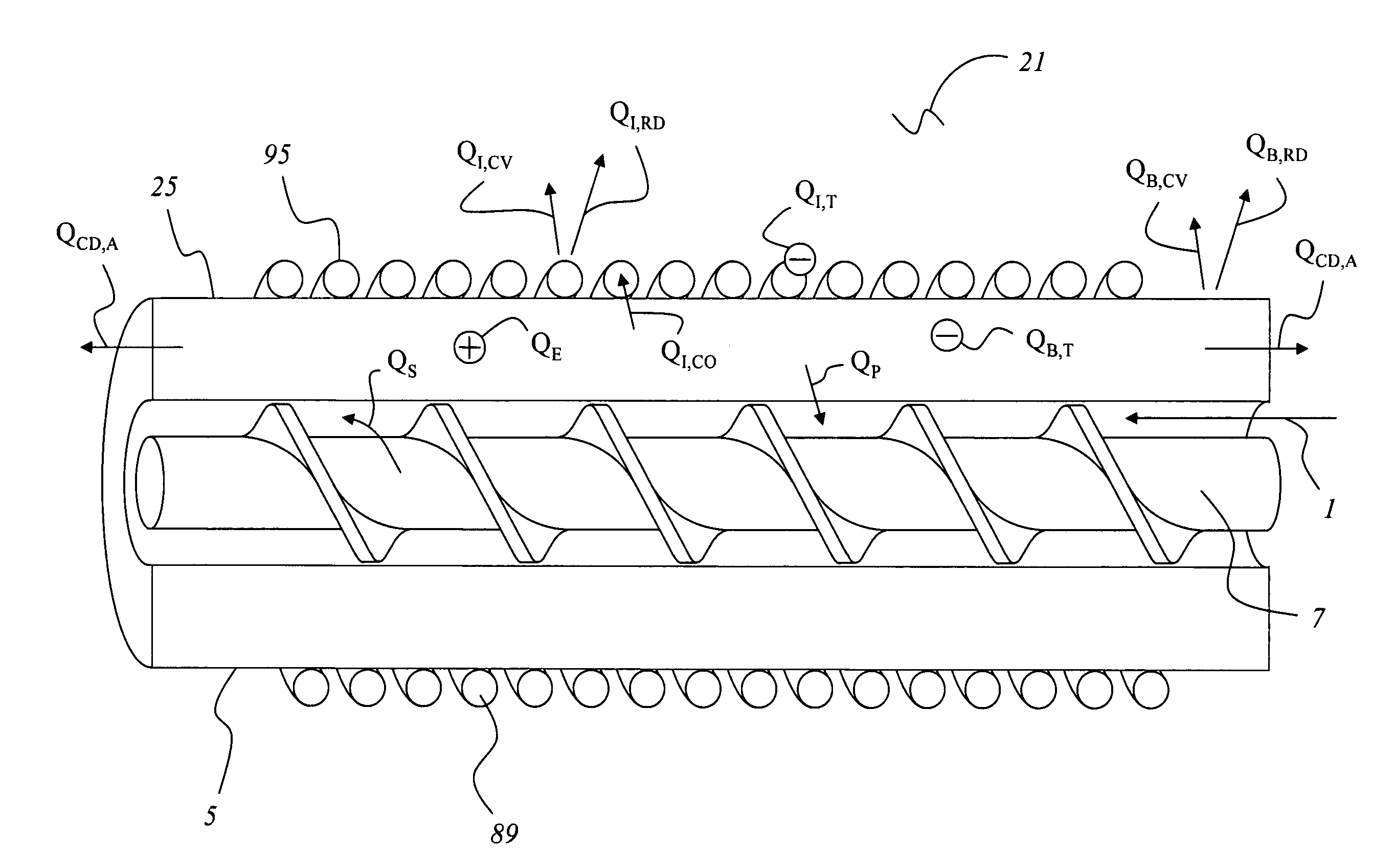
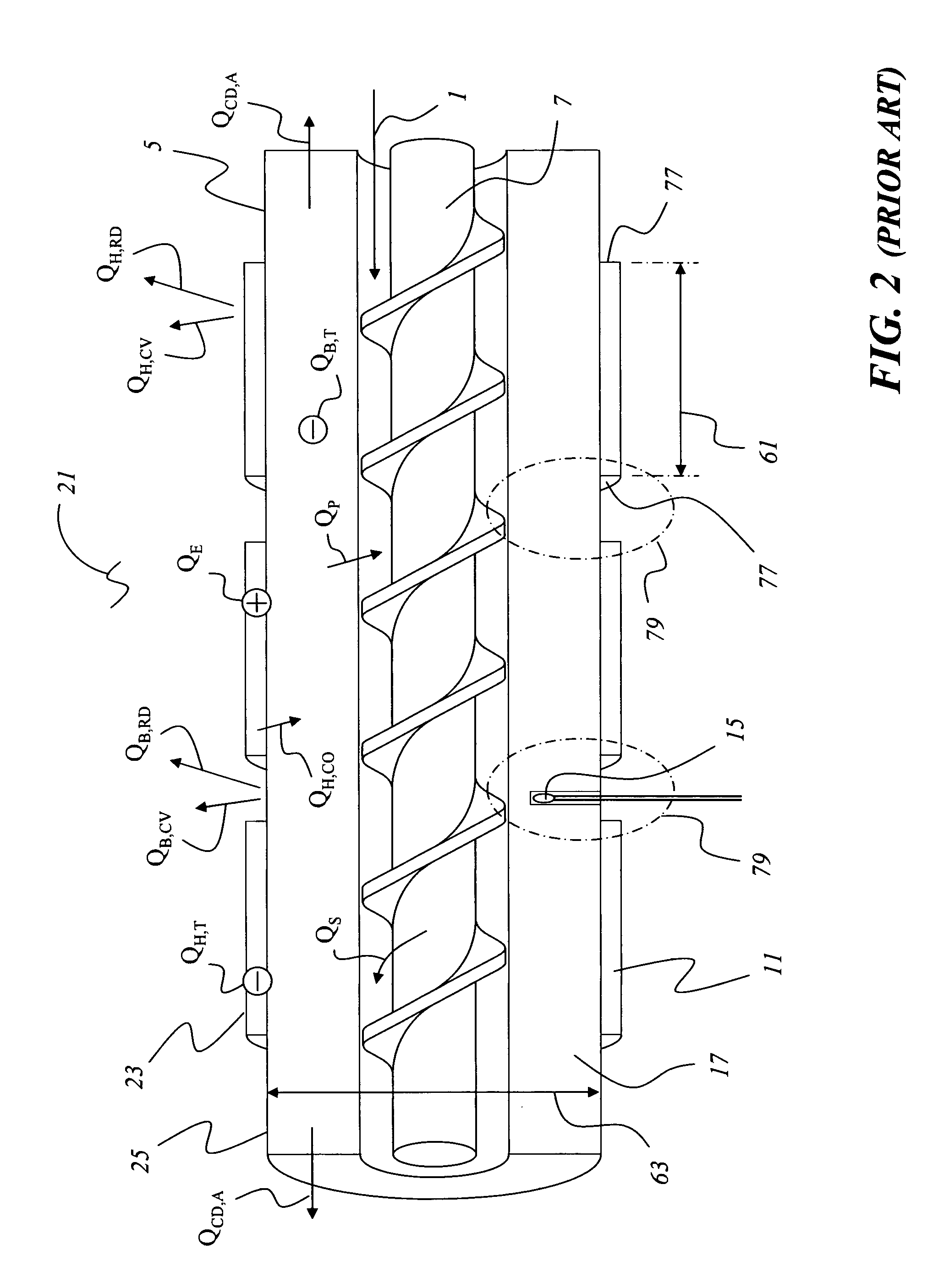
[0054]This discussion begins with reference to FIGS. 2 and 12 to make a comparison of some of the primary differences between heating of workpieces, such as barrels 5, with conventional resistance heaters 11 versus induction heaters with windings 89. Notably, the induction heater generates heat QE directly within the workpiece, while resistance heating must drive heat QH,CO across the contact interface between the resistance heater 11 and the barrel 5. In practice, this allows induction heating to heat the barrel 5 more quickly, even when the windings 89 are in thermal contact therewith. However, the induction windings 89 being in thermal contact with the barrel 5 will create additional thermal mass in the apparatus that will, like that of resistance heaters 11, absorb heat QI,T, thereby slowing the thermal response of the system. Even if the windings 89 do not generate significant resistive heat within themselves, heat QI,CO will conduct across the interface between the heated barr...


PUM

PropertyMeasurementUnit
Frequencyaaaaaaaaaa
Lengthaaaaaaaaaa
Electrical conductivityaaaaaaaaaa

Abstract

Disclosed herein is an apparatus and method with inductive heating of an electrically conductive workpiece such as a barrel used in molding or extrusion, having a layer of thermal insulation interposed between the induction windings and the workpiece, and using alternating current (AC) at an elevated frequency. Further, variable pitch induction windings may be used to generate a non-uniform and calculated heat input profile, such as to compliment the configuration of a screw for transporting material through the barrel.

Description

FIELD OF THE INVENTION[0001]This invention relates to an apparatus and method for heating an electrically conductive workpiece by inductive heating. More particularly this invention relates to inductive heating of a ferrous workpiece, such as an extrusion or molding barrel, using alternating current (AC) at an elevated frequency. While the application of the invention to barrel heating is described in detail herein, this invention can include the heating of any workpiece through which material flows, provided said workpiece is responsive to AC inductive heating and provided said workpiece can be substantially surrounded by an induction coil and an interposed thermal insulating layer.BACKGROUND OF THE INVENTION[0002]Referring to FIGS. 1 and 2, it is commonly known how extruders and molding machines can take fluids or solids and more commonly the latter, such as plastic or magnesium, in such forms as pellets, powder, granules, or chips, (hereinafter collectively referred as processed ...

Claims


Application Information

Patent Timeline
IPC IPC(8): B29C47/80H05B6/14B29C48/875B29C48/92
CPCH05B6/44H05B6/107B29C48/875B29C48/681B29C48/92B29C2948/92704B29C48/6803B29C48/832
Inventor TAYLOR, BRUCE F.KADYKOWSKI, ROBERTLARIVE, RENELECLERC, ELISABETHLARIVE, DANYWOMER, TIMOTHY W.
Owner COMAINTEL
Why Eureka
Try Eureka