
Integrated coal gasification combined cycle plant

Inactive Publication Date: 2008-06-19
MITSUBISHI HEAVY IND LTD
View PDF19 Cites 15 Cited by
  • Summary
  • Abstract
  • Description
  • Claims
  • Application Information

AI Technical Summary

Benefits of technology

[0012]Accordingly, the present invention has been conceived in order to solve the above problems, and an object of the present invention is to provide an IGCC plant which can improve the power generation efficiency and, in addition, which can suppress the emission of sulfur components and dust into the atmosphere.

Problems solved by technology

Hence, there have been problems in that the thermal loss is increased and the power generation efficiency of the IGCC system is degraded.
As a result, the clean-up system becomes complicated, and costs for maintenance and the like are increased, thus the economical efficiency is deteriorated.
Furthermore, the sulfur components remaining in a gas turbine exhaust gas are partly made to react with ammonia supplied in a selective catalytic reduction (SCR) system to form ammonium sulfate particulate dust, and subsequently the dust is discharged without being removed, which is undesirable.
However, in the IGCC plants disclosed in Japanese Patent Nos. 2733188 and 2954972, SO3 and dust primarily composed of ammonium sulfate cannot be removed, and as a result, there has been a problem in that the sulfur components and the dust have not been sufficiently removed.

Method used


Image

  • Integrated coal gasification combined cycle plant
  • Integrated coal gasification combined cycle plant
  • Integrated coal gasification combined cycle plant

Examples


first embodiment

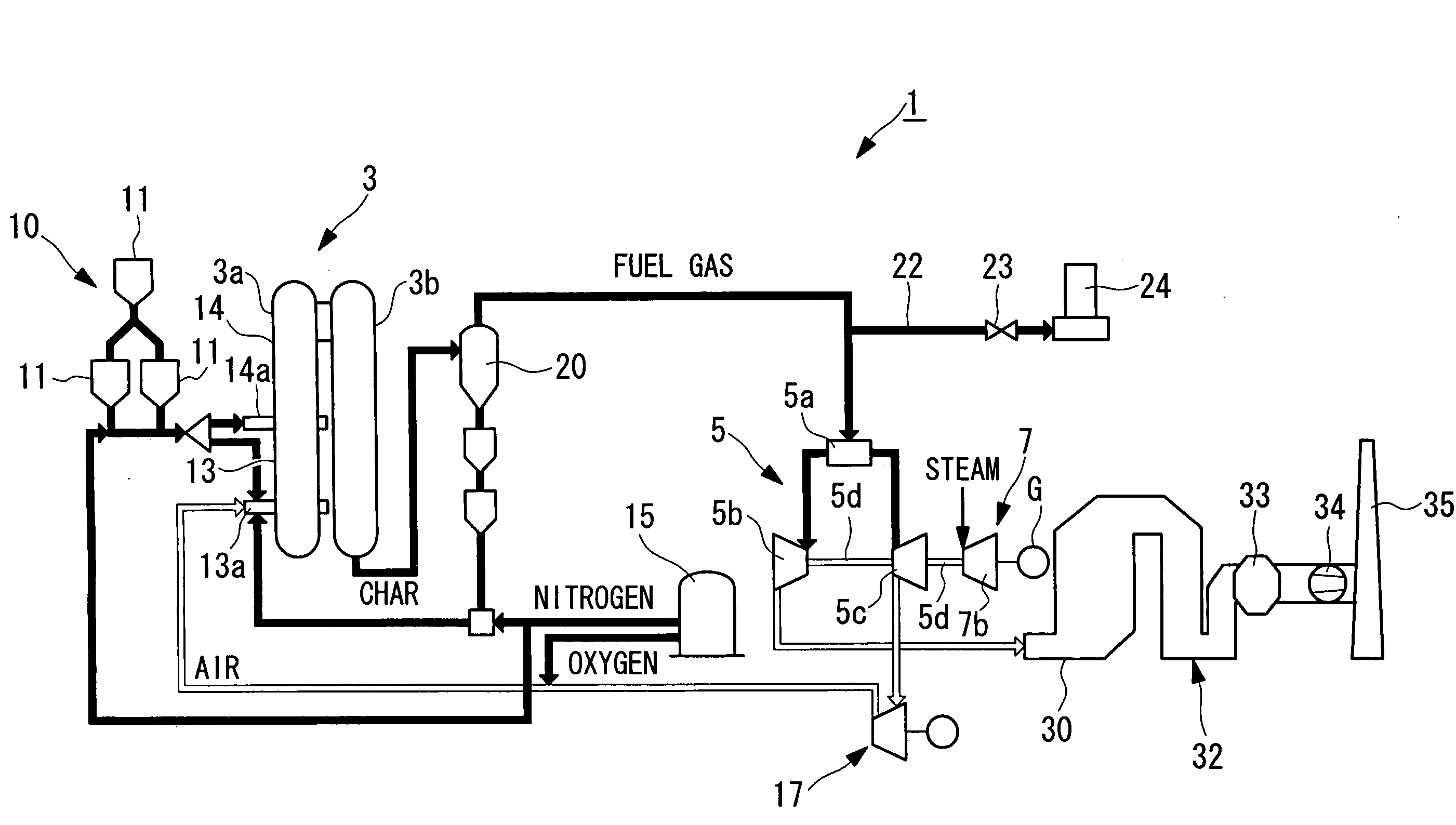
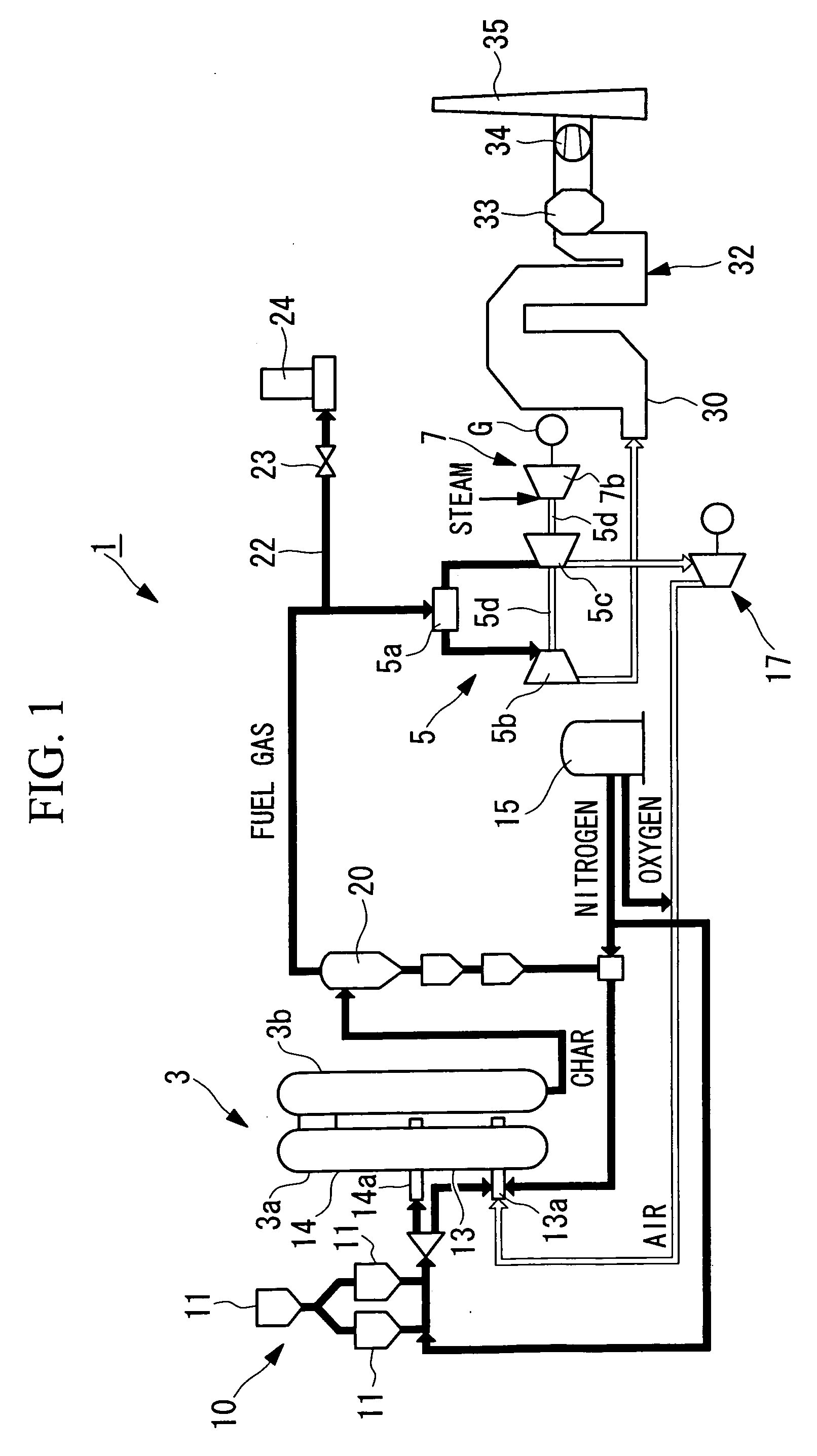
[0029]Hereinafter, a first embodiment of an IGCC plant according to the present invention will be described with reference to FIG. 1.

[0030]As shown in FIG. 1, an IGCC plant 1 of this embodiment, using coal as fuel, primarily includes a coal gasifier 3, a gas turbine system 5, a steam turbine system 7, and an exhaust heat recovery boiler 30.

[0031]A coal supply system 10 for supplying pulverized coal to the coal gasifier 3 is provided at an upstream side thereof. This coal supply system 10 has a pulverizer (not shown) which pulverizes raw coal into pulverized coal having a particle size of several to several hundreds of micrometers and is designed so that the pulverized coal thus pulverized is stored in a plurality of hoppers 11.

[0032]The pulverized coal stored in the hoppers 11 is fed at a constant flow rate to the coal gasifier 3 together with nitrogen gas supplied from an air separation device 15.

[0033]The coal gasifier 3 has a coal gasification section 3a formed so that a gas flow...

second embodiment

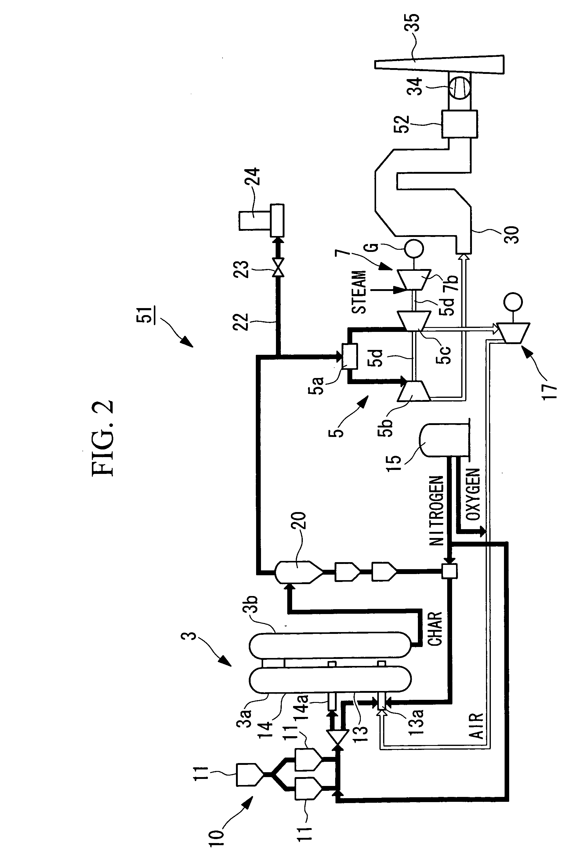
[0069]Next, a second embodiment of the present invention will be described with reference to FIG. 2.

[0070]Although the basic structure of an IGCC plant according to this embodiment is similar to that of the first embodiment, the structure at the downstream side of the exhaust heat recovery boiler is different from that of the first embodiment. Hence, in this embodiment, only the structure at the downstream side of the exhaust heat recovery boiler is described with reference to FIG. 2, and descriptions of the coal gasifier and the like will be omitted.

[0071]In addition, the same reference numerals as in the first embodiment designate the same constituent elements of this embodiment, and a description thereof is omitted.

[0072]An IGCC plant 51 of this embodiment primarily includes the coal gasifier 3, the gas turbine system 5, the steam turbine system 7, and the exhaust heat recovery boiler 30.

[0073]An activated-carbon desulfurization device (desulfurization device) 52 is provided down...


PUM


Abstract

An IGCC plant which can improve the power generation efficiency and which can suppress the emission of sulfur components and dust into the atmosphere is provided. The IGCC plant described above has a coal gasifier for converting pulverized coal to a syngas; an exhaust heat recovery boiler generating steam; a gas turbine system which is operated by the syngas and which supplies a combustion exhaust gas to the exhaust heat recovery boiler; a steam turbine system operated by the steam generated by the exhaust heat recovery boiler; a power generator connected to the gas turbine system and / or the steam turbine system; a desulfurization device for removing sulfur components from the combustion exhaust gas discharged from the exhaust heat recovery boiler; and a wet-type electric precipitator for removing sulfur components and dust.

Description

[0001]This application is based on Japanese Patent Application No. 2004-188888, the content of which is incorporated herein by reference.BACKGROUND OF THE INVENTION[0002]1. Field of the Invention[0003]The present invention relates to an integrated coal gasification combined cycle system plant.[0004]2. Description of Related Art[0005]In a heretofore known integrated coal gasification combined cycle system (hereinafter referred as “IGCC” in some cases), coal as a solid fuel is converted into a gas by a coal gasifier and is then used for a gas turbine combined power generation system. The IGCC has the following advantages. For example, coal resources, which have abundant reserves, are used; compared to a conventional thermal power generation using pulverized coal, the thermal efficiency is high and the amount of emitted air pollutants such as CO2 is small; and since ash is discharged in the form of glassy molten slag, the volume of the ash is decreased. Accordingly, the IGCC was develo...

Claims


Application Information

Patent Timeline
IPC IPC(8): F02C3/00
CPCF02C3/28Y02E20/16Y02E20/18
Inventor YOSHIDA, NAOSHIGE
Owner MITSUBISHI HEAVY IND LTD
Learn More