
Mechanical scanner

a scanner and mechanical technology, applied in the field of mechanical scanners, can solve problems such as the increase in the mass of the wafer holder, and achieve the effect of reducing the mass

Inactive Publication Date: 2008-06-19
APPLIED MATERIALS INC
View PDF22 Cites 26 Cited by
  • Summary
  • Abstract
  • Description
  • Claims
  • Application Information

AI Technical Summary

Benefits of technology

The present invention provides a mechanical scanner for ion implantation of a substrate that has reduced mass. The scanner includes a hexapod with movable legs that allow the substrate to be scanned and tilted in a controlled manner. The scanner also includes a base with a cut-out section to allow ions to pass through. The use of a hexapod provides a rigid structure with precise movements and high stability. The technical effects of the invention include faster scanning and lower vibration of the ion implanter.

Problems solved by technology

Further, a conventional mechanical scanner used in ion implantation needs two motors mounted on top of each other to control the movement of the wafer holder, which can result in an increase in mass of the wafer holder.

Method used


Image

  • Mechanical scanner
  • Mechanical scanner
  • Mechanical scanner

Examples


Embodiment Construction

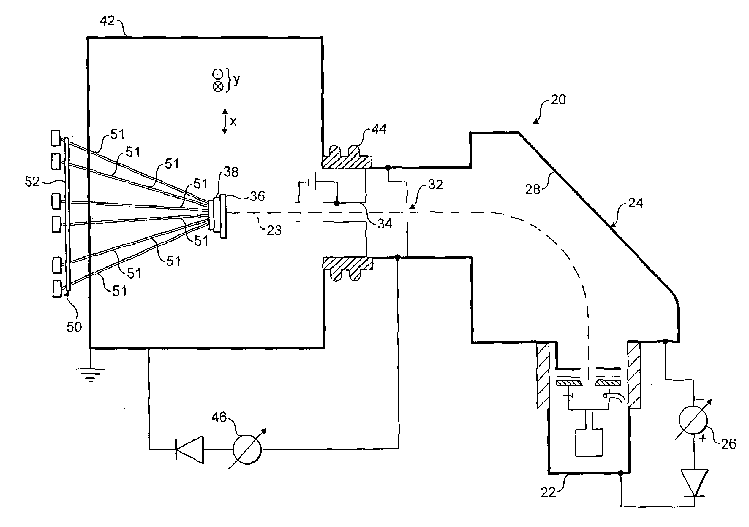
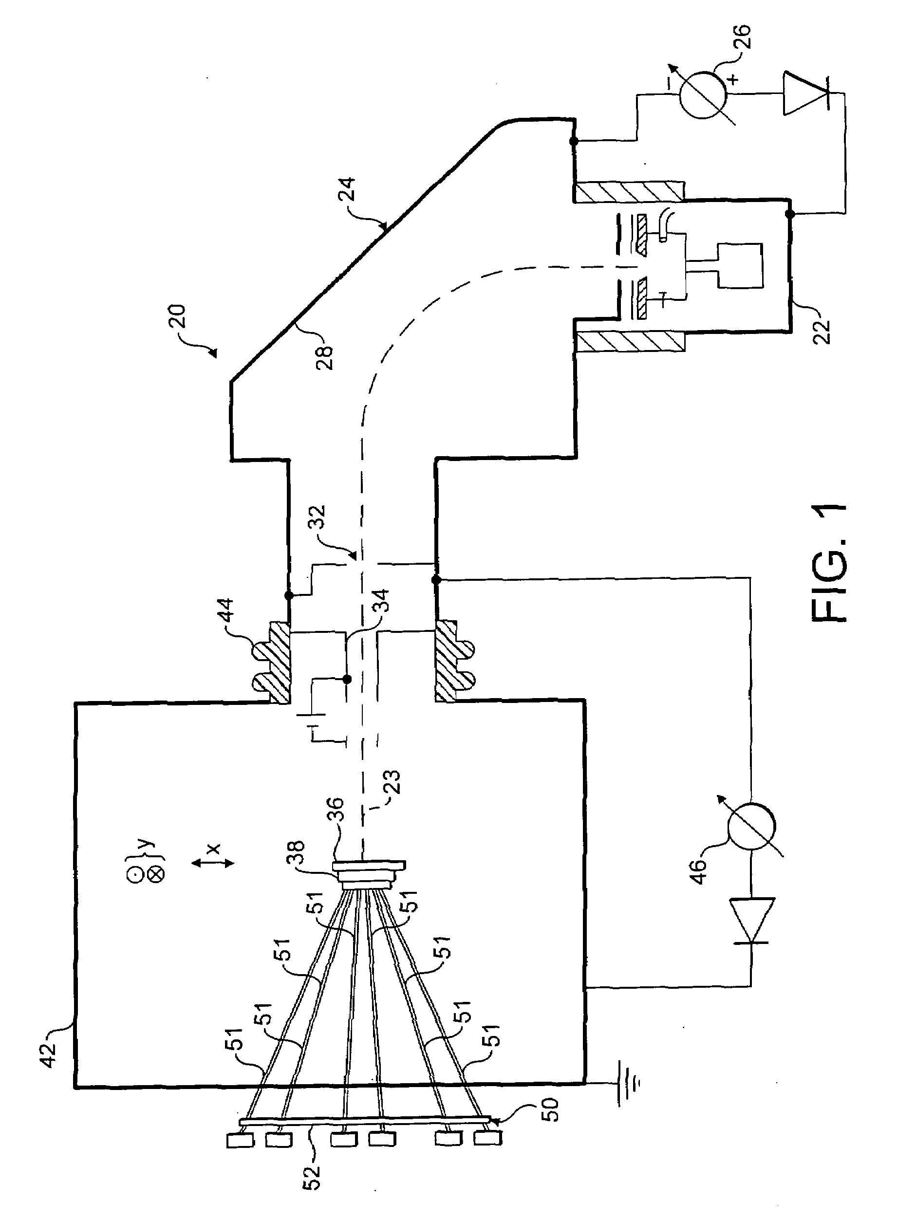
[0034]FIG. 1 shows a typical ion implanter 20 comprising an ion beam source 22 such as a Freeman or Bernas ion source that is supplied with a pre-cursor gas for producing an ion beam 23 to be implanted into a wafer 36. The ions generated in the ion source 22 are extracted by an extraction electrode assembly. A flight tube 24 is electrically isolated from the ion source 22 and a high-tension power supply 26 supplies a potential difference therebetween.

[0035]The potential difference between the flight tube 24 and the ion source 22 causes positively charged ions to be extracted from the ion source 22 into the flight tube 24. The flight tube 24 includes a mass-analysis arrangement comprising a mass-analysing magnet 28 and a mass-resolving slit 32. Upon entering the mass-analysis apparatus within the flight tube 24, the electrically charged ions are deflected by the magnetic field of the mass-analysis magnet 28. The radius and curvature of each ion's flight path is defined, through a con...


PUM

PropertyMeasurementUnit
massaaaaaaaaaa
diameteraaaaaaaaaa
diameteraaaaaaaaaa

Abstract

A mechanical scanner for ion implantation of a substrate, the mechanical scanner comprising a hexapod with a movable platform for holding the substrate, wherein the hexapod is arranged to have six degrees of freedom to allow the movable platform to be traversed relative to an ion beam along a predetermined path.

Description

FIELD OF THE INVENTION[0001]The present invention relates to a mechanical scanner, and in particular a mechanical scanner for ion implantation of a substrate.BACKGROUND OF THE INVENTION[0002]Ion implanters are commonly used in the manufacture of semiconductor products for implanting ions in semiconductor substrates to change the conductivity of the material in predefined regions. Ion implanters generally include an ion beam generator for generating a beam of ions, a mass analyser for selecting a particular specie of ions in the ion beam and means to direct the ion beam onto a target substrate. To allow uniformity of ion implantation typically an ion beam is scanned across the surface of a substrate. As such, the cross sectional area of the ion beam is typically less than the surface area of the substrate, which necessitates traversal of the ion beam over the substrate in a one or two-dimensional scan so that the ion beam covers the whole surface of the substrate. Three two dimension...

Claims


Application Information

Patent Timeline
Patent Type & Authority Applications(United States)
IPC IPC(8): G01K1/08
CPCB25J17/0216F16M11/043F16M11/121F16M11/18H01J2237/20285H01J37/20H01J37/3171H01J2237/20207H01J2237/20228F16M11/32H01J37/30H01L21/265
Inventor SMICK, THEODOREHORNER, RONALDJEN, CAUSON
Owner APPLIED MATERIALS INC
Learn More