Charged-particle-beam processing using a cluster source

a charge-particle beam and cluster source technology, applied in the field of charge-particle beam processing, can solve the problems of affecting the surface of workpieces, affecting the workpiece, and the potential for surface damage or alteration, so as to reduce the damage to the surface

Active Publication Date: 2008-06-19
FEI CO
View PDF69 Cites 54 Cited by
  • Summary
  • Abstract
  • Description
  • Claims
  • Application Information

AI Technical Summary

Benefits of technology

[0017]An object of the invention is to deposit onto or etch a work piece surface using a cluster beam to reduce surface damage.
[0018]This invention includes using a cluster ion source to etch a surface or to deposit material. Using clusters typically reduces substrate damage compared to using individual ions. The invention is particularly useful for depositing a protective layer for charged-particle beam processing. In some embodiments, a precursor gas is decomposed by a cluster beam to deposit a protective layer. In other embodiments, the components of the cluster deposit onto the work piece surface to provide a protective layer for charged particle beam processing. Embodiments of the invention also include systems that allow for deposition of a protective layer using a cluster source and for additional charged particle beam processing.

Problems solved by technology

When a charged-particle beam impacts a surface, there is the potential for damage or alteration of the surface.
Gallium ions are relatively heavy, and a gallium ion accelerated through a typical 30,000 volts will inevitably alter the work piece surface.
Such estimates are not always accurate because of the variation in the alteration by the charged-particle beam.
The scanning causes damage to the surface.
When the region of interest is located and the beam begins to mill a trench, there is additional damage to the work piece because the edges of the beam are not perfectly sharp.
That is, the beam is typically Gaussian shaped, and the ions in the tail of the Gaussian distribution will damage the work piece at the edge of the trench.
Damage has been found not just on fragile materials, but also on relatively hard materials.
Charged-particle-beam-assisted deposition is relatively slow and, in some processes, up to sixty percent of the total processing time is consumed in deposition of the protective layer.
Even though that period of time may be small, it can be large enough to allow a significant amount of material to be removed, which causes the accuracy of the cross-sectional analysis to be compromised.
Electron and laser beams can be used to generate secondary electrons to decompose a precursor gas to deposit a protective layer, but those beams may also damage the underlying surface—especially when they are at sufficient energy and / or current density levels for achieving favorable processing time.
It is generally not practical to use such beams because deposition will be too slow if the beams are sufficiently “weak” to avoid harm to the underlying surface.
Physical vapor deposition (“PVD”) sputter methods could be used to deposit protective layers in some applications, but they normally cannot be utilized for production control applications in wafer fabrication facilities because such methods cannot be used to locally apply a deposition layer onto a targeted part of the wafer surface.
This method, however, is time consuming.
This method is also time consuming.
Using a brush to apply the layer can damage the substrate and cannot provide a localized layer.
The area affected by the felt tip is very large compared to the sub-micron features of modern integrated circuits, and the positioning accuracy of the ink is insufficient.

Method used


Image

  • Charged-particle-beam processing using a cluster source
  • Charged-particle-beam processing using a cluster source
  • Charged-particle-beam processing using a cluster source

Examples


Embodiment Construction

[0025]The following is a detailed description of example embodiments of the invention depicted in the accompanying drawings. The example embodiments are in such detail as to clearly communicate the invention. However, the amount of detail offered is not intended to limit the anticipated variations of embodiments; but, on the contrary, the intention is to cover all modifications, equivalents, and alternatives falling within the spirit and scope of the present invention as defined by the appended claims. The detailed descriptions below are designed to make such embodiments obvious to a person of ordinary skill in the art.

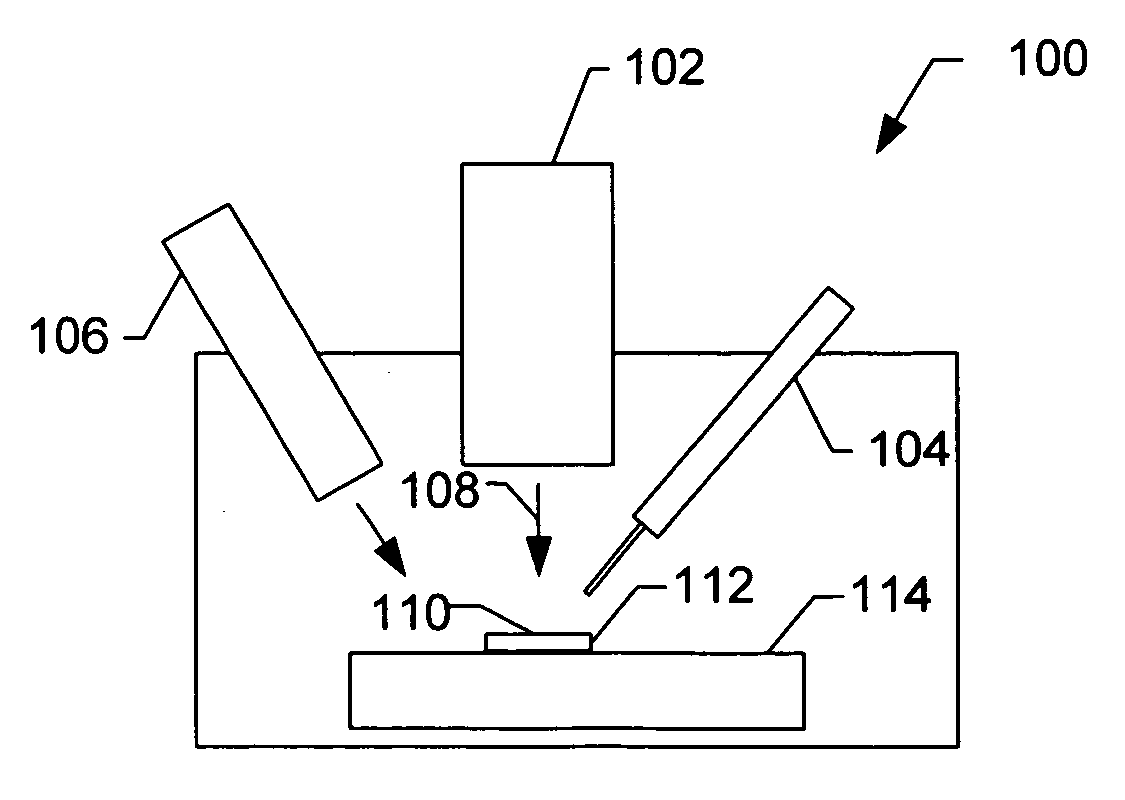
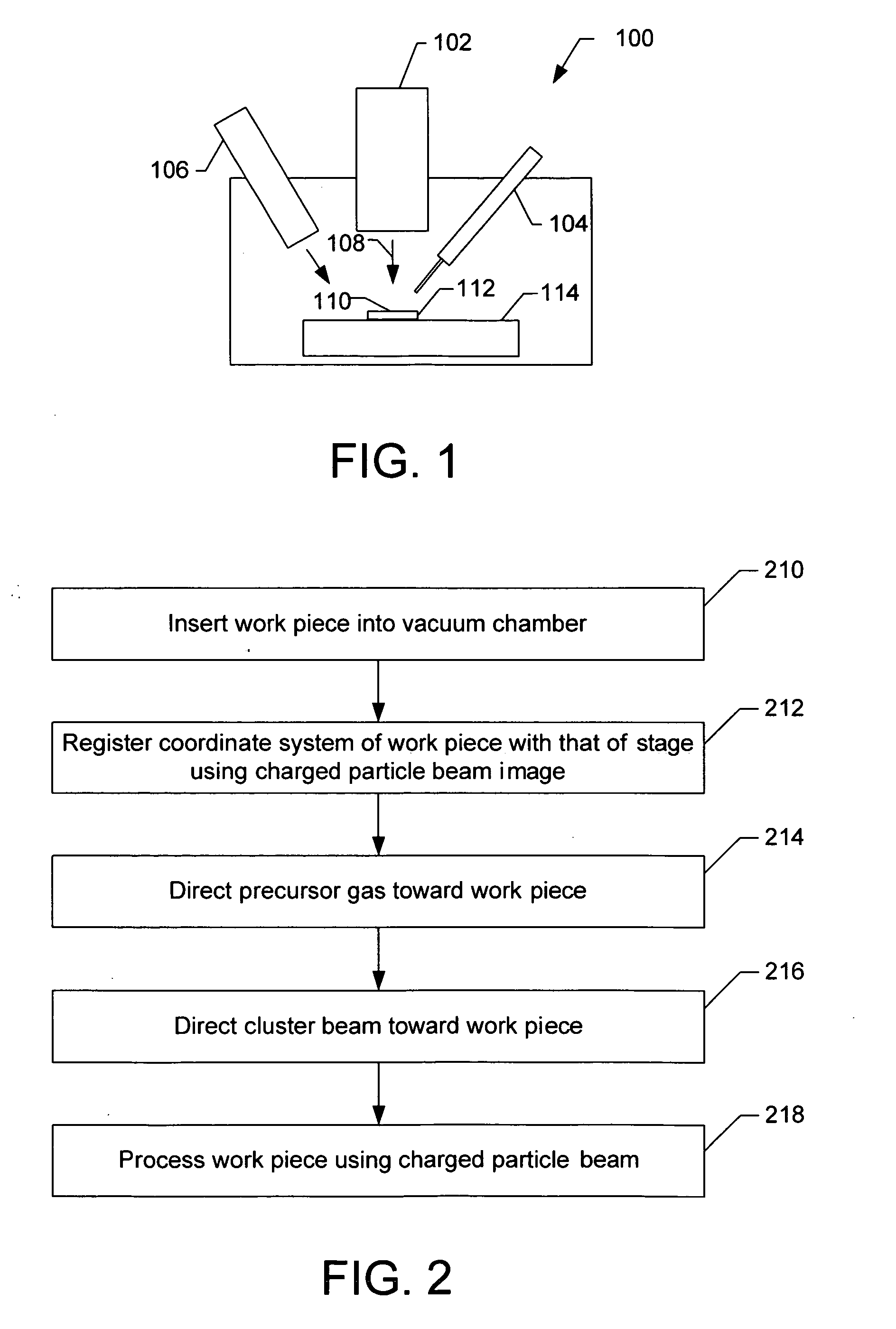
[0026]In some embodiments of the invention, a cluster beam provides energy to decompose a precursor gas to deposit a layer, while minimizing damage to the work piece surface. The cluster beam can also be used to etch the work piece surface, optionally with an etch-enhancing gas. In other embodiments, a cluster beam directly deposits a protective layer for charged part...


PUM


Abstract

A cluster source is used to assist charged particle beam processing. For example, a protective layer is applied using a cluster source and a precursor gas. The large mass of the cluster and the low energy per atom or molecule in the cluster restricts damage to within a few nanometers of the surface. Fullerenes or clusters of fullerenes, bismuth, gold or Xe can be used with a precursor gas to deposit material onto a surface, or can be used with an etchant gas to etch the surface. Clusters can also be used to deposit material directly onto the surface to form a protective layer for charged particle beam processing or to provide energy to activate an etchant gas.

Description

TECHNICAL FIELD OF THE INVENTION[0001]The present invention relates to charged-particle-beam processing.BACKGROUND OF THE INVENTION[0002]Charged-particle beams, such as ion beams and electron beams, are used for processing work pieces in nanotechnology because charged-particle beams can form very small spots. For example, focused ion beam systems are able to image, mill, deposit, and analyze with sub-micron precision. Focused ion beam systems are commercially available, for example, from FEI Company, Hillsboro, Oreg., the assignee of the present application. The ions can be used to sputter, that is, physically eject, material from a work piece to produce features, such as trenches, in the work piece. An ion beam can also be used to activate an etchant gas to enhance sputtering, or to decompose a precursor gas to deposit material near the beam impact point. An ion beam can also be used to form an image of the work piece, by collecting secondary particles ejected by the impact of the ...

Claims


Application Information

Patent Timeline
Patent Type & Authority Applications(United States)
IPC IPC(8): G21G5/00
CPCH01J37/3056H01J37/3178H01J2237/006H01J2237/0812H01J2237/0815H01L21/67069H01J2237/31732H01J2237/3174H01J2237/31742H01J2237/31744H01L21/306H01J2237/3142
Inventor CHANDLER, CLIVESMITH, NOEL
Owner FEI CO
Why Eureka
Try Eureka