Process of Producing Patterned Birefringent Product

a technology of patterned birefringent and product, which is applied in the direction of polarising elements, instruments, other domestic articles, etc., can solve the problems of difficult simple copying with a copier, difficult visible identification, and inability to manufacture, etc., to achieve easy pattern identification, reduce the number of optical compensation sheets of lcd, and produce a high-resolution patterned birefringent product. the effect of excellent heat resistan

Active Publication Date: 2008-06-19
FUJIFILM CORP
View PDF9 Cites 84 Cited by
  • Summary
  • Abstract
  • Description
  • Claims
  • Application Information

AI Technical Summary

Benefits of technology

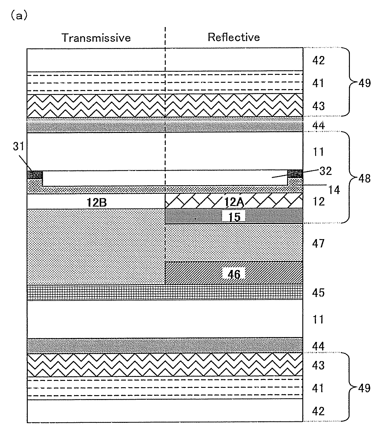
[0017]An object of the present invention is to provide a process and material which are useful for readily producing a patterned birefringent product excellent in resolution and heat-resistance. Another object of the present invention is to provide a process and material of producing pattern which is almost transparent and colorless when observed through no polarizing plate and becomes easily pattern-identifiable when observed through a polarizing plate. Further object of the present invention is to provide a process useful for producing a substrate for liquid crystal display device having patterned retardation. Another object of the present invention is to provide a substrate for liquid crystal display device contributing to the reduction of the number of optical compensation sheets of LCD, particularly semi-transmissive LCD, and thickness of LCD.

Problems solved by technology

With holograms, an authenticity determination can readily be made visually, and simple copying with a copier is difficult.
To avoid forgery, a configuration is possible in which a machine is used to more precisely detect the direction and intensity of refracted light, but visible identification has become difficult.
By contrast, birefringence patterns can be readily identified using polarizing plates and the manufacturing technique is not that widespread.
Thus, forgeries are difficult, and birefringence patterns are suited to be used as authentication images.
However, patterns produced by techniques in which birefringence is reduced with heat, as set forth above, all have the drawback of poor heat resistance.
That is, there is a risk that when heat is applied to a portion in which birefringence remains, the birefringence of that portion will end up decreasing.
Further, in techniques employing thermal heads and heat stamps, since it is difficult to impart different thermal conductivities in the direction of thickness and the in-surface direction, it is extremely difficult to create a pattern at a resolution lower than the thickness of the film.
Heating with a laser permits the creation of high-resolution patterns, but there is a problem in that the drawing of fine patterns by scanning with a laser is time-consuming.
However, the resistance to light of the pattern that is produced by this technique is low, rendering the pattern unsuitable as a birefringence pattern for use in optical elements in particular.
However, in this method, controlling the state of orientation of the liquid crystals prior to fixation requires conducting multiple exposures while carefully controlling the temperature of the overall system, presenting a problem in the form of a demanding manufacturing process.
Therefore, many problems arise: the LCD becomes thick because it requires two or more optically compensation sheets laminated together in various angles; the laminated structure of the optically compensation sheets becomes expensive because lamination by roll to roll method is not possible; and viewing angle becomes asymmetric because the angles of the optically compensation sheets are various.
However, this method has a problem of burden in the process, because it needs three ultraviolet ray irradiations including two polarized ultraviolet ray irradiations, and two coatings of optically alignment layer and polymerizable liquid crystalline layer.
Therefore, the method has not come into practical use.
Further, in this method, the two alignment domains must have the same retardations, and thus flexibility of designing the switching of LCD is limited.

Method used


Image

  • Process of Producing Patterned Birefringent Product
  • Process of Producing Patterned Birefringent Product
  • Process of Producing Patterned Birefringent Product

Examples


example 1

Production of Birefringence Pattern Builder and Patterned Birefringent Product

[0335](Production of Sample TRC-1 for Evaluation of Optically Anisotropic Layer and Transfer Material for Producing Birefringence Pattern TR-1)

[0336]To the surface of a temporary support formed of a 100-μm-thick polyethylene terephthalate film with easily adhesible property (COSMOSHINE A4100 from Toyobo Co., Ltd.), the coating liquid for a dynamic property control layer, CU-1, and the coating liquid for an alignment layer, AL-1, in this order were applied by using a wire bar coater and dried. The obtained layers had dry film thickness of 14.6 μm and 1.6 μm, respectively. Next the coating liquid for optically anisotropic layer, LC-1, was applied to the surface using a wire bar coater, dried under heating at 105° C. on the surface of the film for 2 minutes, to thereby obtain a layer of a liquid crystal phase. The coated layer was then illuminated in the air atmosphere by ultraviolet radiation by using a 160 ...

example 2

Birefringence Pattern Builder with Plural Optically Anisotropic Layers Laminated)

(Production of Transfer Material for Producing Birefringence Pattern TR-5)

[0360]Transfer material for producing birefringence pattern TR-5 was produced in a similar manner to that of TR-1 except that the thickness of the optically anisotropic layer was 3.6 μm.

(Production of Birefringence Pattern Builder BPM-5 of the Present Invention)

[0361]A non-alkali glass substrate was cleaned using a rotating nylon-haired brush while spraying a glass cleaner solution conditioned at 25° C. by a shower for 20 seconds. After showered with purified water, the substrate was sprayed with a silane coupling solution (0.3% aqueous solution of N-β-(aminoethyl)-γ-aminopropyl trimethoxysilane, trade name: KBM-603, Shin-Etsu Chemical Co., Ltd.) by a shower for 20 seconds, and then cleaned with a shower of purified water. The obtained substrate was then heated in a substrate preheating heater at 100° C. for 2 minutes.

[0362]The ab...

example 3

Production of Multi-Color Pattern by Repeating Transfer-Light Exposure-Baking Plural Times

(Production of Transfer Material for Producing Birefringence Pattern TR-6)

[0368]Transfer material for producing birefringence pattern TR-6 was produced in a similar manner to that of TR-1 except that the thickness of the optically anisotropic layer was 1.2 μm.

[0369](Production of Multi-Color Birefringence Pattern BP-6 of the Present Invention)

[0370]A non-alkali glass substrate was cleaned using a rotating nylon-haired brush while spraying a glass cleaner solution conditioned at 25° C. by a shower for 20 seconds. After showered with purified water, the substrate was sprayed with a silane coupling solution (0.3% aqueous solution of N-β-(aminoethyl)-γ-aminopropyl trimethoxysilane, trade name: KBM-603, Shin-Etsu Chemical Co., Ltd.) by a shower for 20 seconds, and then cleaned with a shower of purified water. The obtained substrate was then heated in a substrate preheating heater at 100° C. for 2 mi...


PUM

PropertyMeasurementUnit
retardation disappearance temperatureaaaaaaaaaa
temperature in-plane retardationaaaaaaaaaa
temperatureaaaaaaaaaa

Abstract

A process of readily producing a patterned birefringent product excellent in resolution and heat-resistance is provided. Said process comprises at least the following steps [1] to [3] in order:
    • [1] preparing a birefringence pattern builder which comprises an optically anisotropic layer comprising a polymer, and said optically anisotropic layer has a retardation disappearance temperature in the range higher than 20° C.,
    • at said retardation disappearance temperature in-plane retardation becomes 30% or lower of the retardation at 20° C. of the same optically anisotropic layer, and
    • said retardation disappearance temperature rises by light exposure;
    • [2] subjecting the birefringence pattern builder to patterned light exposure;
    • [3] heating the laminated structure obtained after the step [2] at 50° C. or higher and 400° C. or lower.

Description

TECHNICAL FIELD[0001]The present invention relates to a process of producing a patterned birefringent product and a patterned birefringent product such as a substrate for a liquid crystal display device produced by said process.RELATED ART[0002]Attempts have been made to industrially exploit birefringence patterns in a variety of forms. Japanese Unexamined Patent Publication (KOKAI) Heisei No. 3-141320 proposes a method for recording images employing birefringence patterns. Birefringence patterns that are normally unidentifiable to the human eye are rendered visible by being sandwiched between two polarizing plates. A technique of actively exploiting birefringence pattern characteristics by “using polarizing plates to render visible what was originally invisible” is disclosed in Japanese Unexamined Patent Publication (KOKAI) No. 2007-1130, which proposes the use of a birefringence pattern as a true authentication image.[0003]Reflection holograms have been exclusively employed in the...

Claims


Application Information

Patent Timeline
Patent Type & Authority Applications(United States)
IPC IPC(8): G02F1/13363B29D11/00G02F1/13
CPCB42D2033/26B42D25/391G02B5/3083G02B5/3016G02B5/30B42D25/364B42D25/455
Inventor AMIMORI, ICHIROKANEIWA, HIDEKIMORISHIMA, SHINICHIYOSHINO, HARUHIKOTOMITA, HIDETOSHI
Owner FUJIFILM CORP
Why Eureka
Try Eureka