Yttria containing thermal barrier coating topcoat layer and method for applying the coating layer

a thermal barrier coating and yttria technology, applied in the direction of wind motor components, liquid fuel engine components, non-positive displacement fluid engines, etc., can solve the problems of foreign object damage, tbc coated hot section engine components are susceptible to various modes of damage, and the thermal conductivity of tbcs formed by these methods is generally lower than a dense ceramic, so as to reduce or eliminate the infiltration of cmas and increase the life of gas turbine engine components

Active Publication Date: 2008-06-19
GENERAL ELECTRIC CO
View PDF17 Cites 62 Cited by
  • Summary
  • Abstract
  • Description
  • Claims
  • Application Information

AI Technical Summary

Benefits of technology

[0012]An embodiment of the present invention provides reduced or eliminated infiltration of CMAS into thermal barrier coatings.
[0013]Y2O3 has similar vapor pressure and deposition chara

Problems solved by technology

TBCs formed by these methods generally have a lower thermal conductivity than a dense ceramic of the same composition as a result of the presence of microstructural defects and pores at and between grain boundaries of the TBC microstructure.
Under service conditions, these TBC coated hot section engine components can be susceptible to various modes of damage, including erosion, oxidation and corrosion from exposure to the gaseous products of combustion, foreign object damage and attack from environmental contaminants.
These environmental contaminants are in addition to the corrosive and oxidative contaminants that result from the combustion of fuel.
However, all of these contaminants can adhere to the surfaces of the hot section components, which are typically thermal barrier coated.
Some contaminants may result in TBC loss over the life of the components.
The CMAS interferes with the compliance of the columnar structure of the TBC resulting in spallation and degradation of the TBC.
In addition, CMAS may infiltrate into dense vertically cracked TBC or into the horizontal splat boundaries of thermally and plasma sprayed microstructures and cause s

Method used


Image

  • Yttria containing thermal barrier coating topcoat layer and method for applying the coating layer
  • Yttria containing thermal barrier coating topcoat layer and method for applying the coating layer
  • Yttria containing thermal barrier coating topcoat layer and method for applying the coating layer

Examples


Embodiment Construction

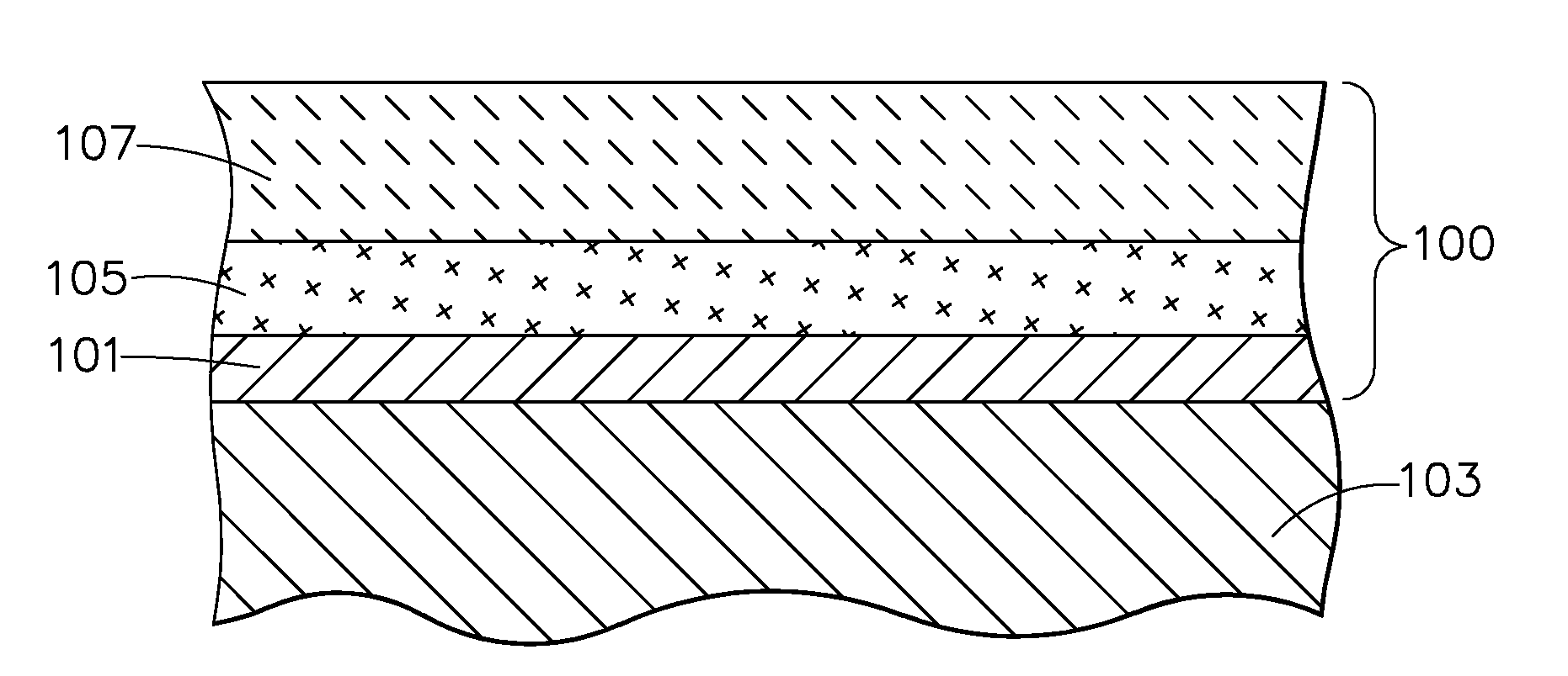
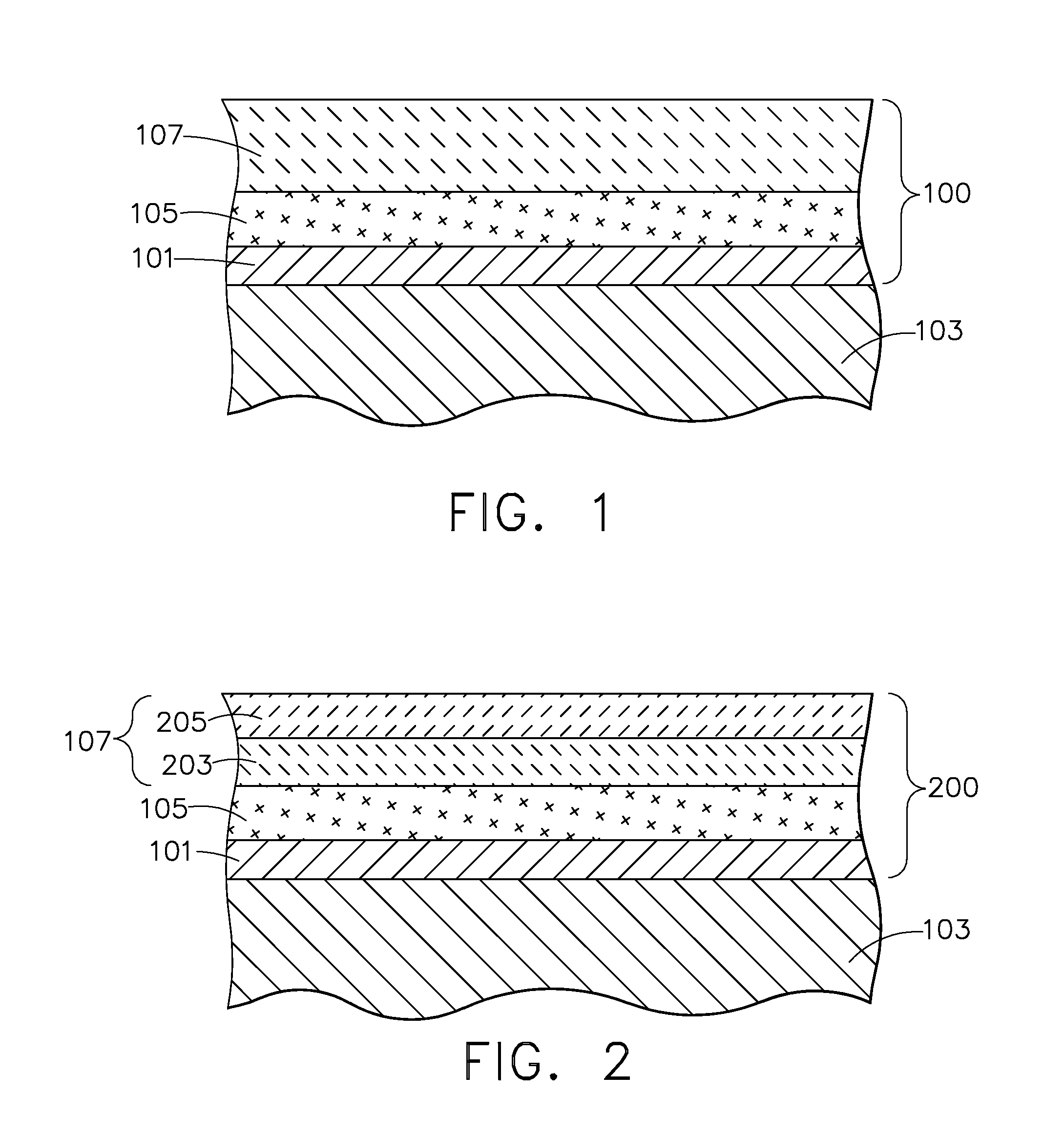
[0021]The present invention is generally applicable to components subjected to high temperatures, and particularly to components such as the high pressure and low pressure turbine vanes (nozzles) and blades (buckets), shrouds, combustor liners and augmentor hardware of gas turbine engines. The invention provides a thermal barrier coating (TBC) system suitable for protecting those surfaces of a gas turbine engine component that are subjected to hot combustion gases. While the advantages of this invention will be described with reference to gas turbine engine components, the teachings of the invention are generally applicable to any component on which a TBC may be used to protect the component from a high temperature environment, particularly environments containing CMAS.

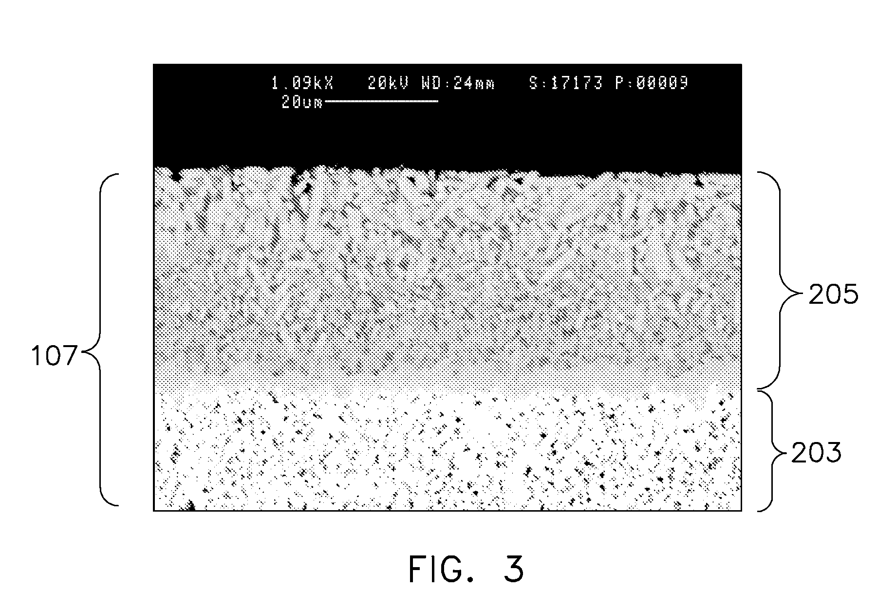
[0022]Coating systems in accordance with exemplary embodiments of this invention are represented in FIGS. 1 and 2. In each embodiment, the coating system 100 is shown as including a metallic bond coat layer 101 that o...


PUM

PropertyMeasurementUnit
Concentrationaaaaaaaaaa

Abstract

A gas turbine engine component and coating system including a superalloy substrate having a coating system disposed thereon. A bond coating may be applied to the substrate. An adherent layer of ceramic material forming a thermal barrier coating is present on the bond coat layer. A topcoat layer overlies the thermal barrier coating. The topcoat layer includes greater than about 20 wt % yttria.

Description

FIELD OF THE INVENTION[0001]The present invention is directed to environmentally resistant thermal barrier coating systems for use in gas turbine engines. In particular, the present invention is directed to a top coating overlying a thermal barrier coating on turbine components of a gas turbine engine that provides resistance to calcium-magnesium-aluminum-silicate containing particulate contamination.BACKGROUND OF THE INVENTION[0002]The use of thermal barrier coatings (TBC) on components such as combustors, high pressure turbine (HPT) blades, vanes and shrouds is increasing in commercial as well as military gas turbine engines. The thermal insulation provided by a TBC enables such components to survive higher operating temperatures, increases component durability, and improves engine reliability. TBC is typically a ceramic material deposited on an environmentally-protective bond coat to form what is termed a TBC system. Bond coat materials widely used in TBC systems include oxidatio...

Claims


Application Information

Patent Timeline
IPC IPC(8): B32B15/00B05D1/36F01D5/14
CPCF01D5/288Y02T50/67Y02T50/671C23C28/321C23C28/3215Y10T428/12611C23C28/345C23C28/3455C23C28/36F05D2300/2118Y10T428/12618C23C28/325Y02T50/60
Inventor DAROLIA, RAMGOPALFU, MING
Owner GENERAL ELECTRIC CO
Why Eureka
Try Eureka