Eureka AIR delivers breakthrough ideas for toughest innovation challenges, trusted by R&D personnel around the world.

Porous anode active material, method of preparing the same, and anode and lithium battery employing the same

a technology of active materials and porous anodes, which is applied in the direction of non-metal conductors, cell components, conductors, etc., can solve the problems of reducing the charge/discharge efficiency or allowing short circuit between the anode and the cathode, the risk of explosion, and the inability to widely use lithium anodes, etc., to achieve excellent charge/discharge characteristics and efficient removal of stress

Active Publication Date: 2008-06-19
SAMSUNG SDI CO LTD
View PDF12 Cites 168 Cited by
  • Summary
  • Abstract
  • Description
  • Claims
  • Application Information

AI Technical Summary

Benefits of technology

[0013]The present invention also provides an anode electrode and a lithium battery comprising the anode active material, which have enhanced charge / discharge efficiency and effective charge / discharge capacity.
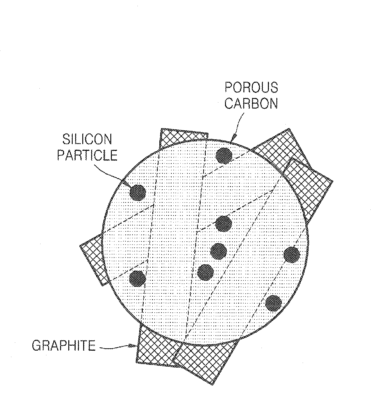
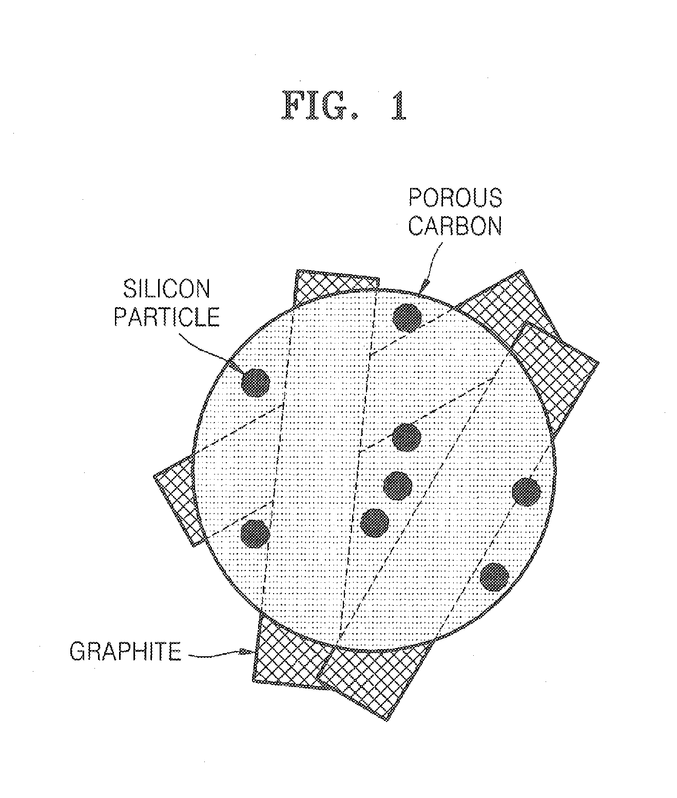
[0025]The anode active material according to an embodiment of the present invention contains pore having a bimodal size distribution, unlike a conventional anode active material without having pores therein. Thus, the anode active material according to an embodiment of the present invention may efficiently remove a stress occurring due to a difference of expansion ratio between a carboneous material and a metallic active material during charging and discharging. Further, the anode electrode and the lithium battery comprising the anode active material have excellent charge / discharge characteristics.

Problems solved by technology

However, when lithium metal is used as an anode, a large amount of lithium dendrites is formed on a surface of the lithium metal during charging, thereby decreasing charge / discharge efficiency or allowing short circuit to occur between the anode and a cathode.
Further, due to instability, i.e., high reactivity of lithium, lithium anodes are sensitive to heat or an impact and have a risk of explosion.
Thus, it is impossible for lithium anodes to be widely used.
Lithium batteries containing carbon anodes essentially have low battery capacity due to a porous structure of carbon.
Thus, even though metal anodes have the above problems, many attempts have been made to increase battery capacity by introducing metals, such as lithium, into anodes.
However, the lithium metal materials have volumetric expansions different from carboneous materials during redox reactions and react with an electrolytic solution.
Further, during the charging and discharging, the metal material reacts with an electrolytic solution and a lifetime of the electrolytic solution decreases, thereby decreasing a lifetime and an efficiency of the battery.
However, it is difficult to solve the above problems due to the charging and discharging only by using the mixture containing the flat powders.
However, the anode is formed by simply assembling them, and thus when the metal particles expand, bonds between the metal particles and the graphite particles are broken.

Method used


Image

  • Porous anode active material, method of preparing the same, and anode and lithium battery employing the same
  • Porous anode active material, method of preparing the same, and anode and lithium battery employing the same
  • Porous anode active material, method of preparing the same, and anode and lithium battery employing the same

Examples


example 1

[0090]2.0 g of silicon powders having an average diameter of 3 μm was added to 5 g of methanol and an ultrasonic wave was irradiated to the mixture in an ultrasonic bath for 10 minutes. Then, while stirring the solution, aminopropyltrimethoxysilane (APS) was slowly added dropwise thereto, and then further stirred for 5 hours. An excess amount of methanol was added to the stirred solution and centrifuged and then a supernatant was removed, which was repeated three times to remove unreacted APS from the solution. The solution was dried at 80° C. to obtain fine silicon particles having their surfaces capped with the alkyl amine.

[0091]5 g of crystalline carbon fibers (VGCFs), 100 mL of 60% nitric acid, and 50 mL of deionized water were placed into a container made of high density polyethylene (HDPE) and milled with zirconia balls for 7 days. The resultant product was centrifuged and dried.

[0092]0.61 g of phenol, 0.13 g of a NaOH solution (20% by weight), and 1.05 g of a formaldehyde sol...

example 2

[0094]A porous anode active material was prepared in the same manner as in Example 1, except that silicon powders having an average diameter of 70 nm were used instead of the silicon powders having an average diameter of 3 μm and that graphite particles (SFG-6, manufactured by TimCal) were used instead of the crystalline carbon fibers (VGCFs).

example 3

[0095]A porous anode active material was prepared in the same manner as in Example 1, except that SiO powders having an average diameter of 5 μm were used instead of the silicon powders having an average diameter of 3 μm and that graphite particles (SFG-6, manufactured by TimCal) were used instead of the crystalline carbon fibers (VGCFs).


PUM

PropertyMeasurementUnit
Temperatureaaaaaaaaaa
Pore sizeaaaaaaaaaa
Pore sizeaaaaaaaaaa

Abstract

Provided are a porous anode active material, a method of preparing the same, and an anode and a lithium battery employing the same. The porous anode active material includes fine particles of metallic substance capable of forming a lithium alloy; a crystalline carboneous substance; and a porous carboneous material coating and attaching to the fine particles of metallic substance and the crystalline carboneous substance, the porous anode active material having pores exhibiting a bimodal size distribution with two pore diameter peaks as measured by a Barrett-Joyner-Halenda (BJH) pore size distribution from a nitrogen adsorption. The porous anode active material has the pores having a bimodal size distribution, and thus may efficiently remove a stress occurring due to a difference of expansion between a carboneous material and a metallic active material during charging and discharging. Further, the anode electrode and the lithium battery comprising the anode active material have excellent charge / discharge characteristics.

Description

CROSS-REFERENCE TO RELATED PATENT APPLICATION[0001]This application claims priority to and the benefit of Korean Patent Application No. 10-2006-0130375, filed on Dec. 19, 2006, in the Korean Intellectual Property Office, the disclosure of which is incorporated herein in its entirety by reference.BACKGROUND OF THE INVENTION[0002]1. Field of the Invention[0003]The present invention relates to a porous anode active material, a method of preparing the same, and an anode and a lithium battery employing the same. More particularly, the present invention relates to a porous anode active material comprising pores having a bimodal size distribution, a method of preparing the same, and an anode and a lithium battery employing the same.[0004]2. Description of the Related Art[0005]Non-aqueous electrolytic secondary batteries using lithium compounds as anodes have high voltages and energy densities, and thus have been actively studied. In particular, vigorous research has been conducted on lithi...

Claims


Application Information

Patent Timeline
IPC IPC(8): H01M4/38B29C67/00H01M4/42H01M4/56H01M4/46H01M4/08
CPCH01M4/133H01M4/134H01M4/1393H01M4/364H01M4/42Y02E60/122H01M4/587H01M4/625H01M10/052H01M2004/021H01M4/466H01M4/38H01M4/386H01M4/387Y02E60/10B82Y30/00H01M4/36
Inventor MAH, SANG-KOOKKIM, HAN-SUIM, DONG-MIN
Owner SAMSUNG SDI CO LTD
Why Eureka
Eureka Blog
Learn More