MRI compatible implantable devices

a technology of implantable devices and compatible implants, which is applied in the direction of internal electrodes, transvascular endocardial electrodes, therapy, etc., can solve the problems of mri posing a threat to patients with implantable devices, patients with metallic implants not being allowed to undergo mri scans, and heating under certain mri scanning conditions

Inactive Publication Date: 2008-06-26
ATALAR ERGIN
View PDF7 Cites 60 Cited by
  • Summary
  • Abstract
  • Description
  • Claims
  • Application Information

AI Technical Summary

Problems solved by technology

MRI may, however, pose a threat to patients that have implantable devices, such as, without limitation, a deep brain stimulation (DBS) device, a pacemaker, a neurostimulator, or a cardio-defibrillator.
Currently, patients with metallic implants are not allowed to undergo an MRI scan.
One of the main reasons for this is the excessive heating caused by the electromagnetic field concentration around the leads of an implant during an MRI procedure.
These results indicate that heating may be hazardous under certain MRI scanning conditions.
However, many modern MRI pulse sequences, such as fast spin-echo or steady-state free precession (SSFP), require high RF power levels and, therefore, there is no guarantee that good quality images can be acquired if RF power is limited.
This patent does not disclose, however, using an electronic switch or a resistive element in parallel with a diode.
Because this patent does not disclose using a series capacitor, a polarization at the lead can occur and cause several problems.
One of the most serious problems is the quick discharge of the battery of the implant.
However, these designs do not guarantee safety with regard to lead heating.
This is because high currents may still flow through long cables and these high currents may cause excessive heating and burns.
However, the electrical to optical and optical to electrical energy conversion efficiency is limited and, therefore, the lifetime of the pulse generator reduces significantly.
Miniaturization of the device also is a difficult task.
Another possible safety problem with MRI is that gradient-induced currents on the implants may cause undesired nerve stimulation with the possibility of cardiac arrest.

Method used


Image

  • MRI compatible implantable devices
  • MRI compatible implantable devices
  • MRI compatible implantable devices

Examples


example 1

Simulations

I. Pacing Pulse Models

[0125]Basic properties of simulations need to be defined before simulation results are provided. In standard stimulator applications, pulse duration changes with an interval of 0.1 ms to 2 ms. In this implementation, pulse duration is applied as 1 msec with a period of 1 sec. Target body part resistance is accepted as 1 KQ. Pulse level is applied as 5 volts.

[0126]a. Diode Resistor Circuit (DRC)

[0127]In order to simulate this implementation, ORCAD PSpice 9.1 Demo (Cadence, 2655 Seely Avenue, San Jose, Calif. 95134, USA) was used. In this simulation, Infineon Technologies BA595 pin diode model was used. A 1 msec pulse was applied in a period of 1 sec on the diode and resistor. As a result of this simulation, a 4.2 volt pulse level was observed on the tip (target body resistance) at 1 msec.

[0128]This result is shown in FIG. 19, which is a simulation result of a DRC embodiment on target body resistance. This result is a unipolar pacing result and one dio...

example 2

I. Experimental Methods

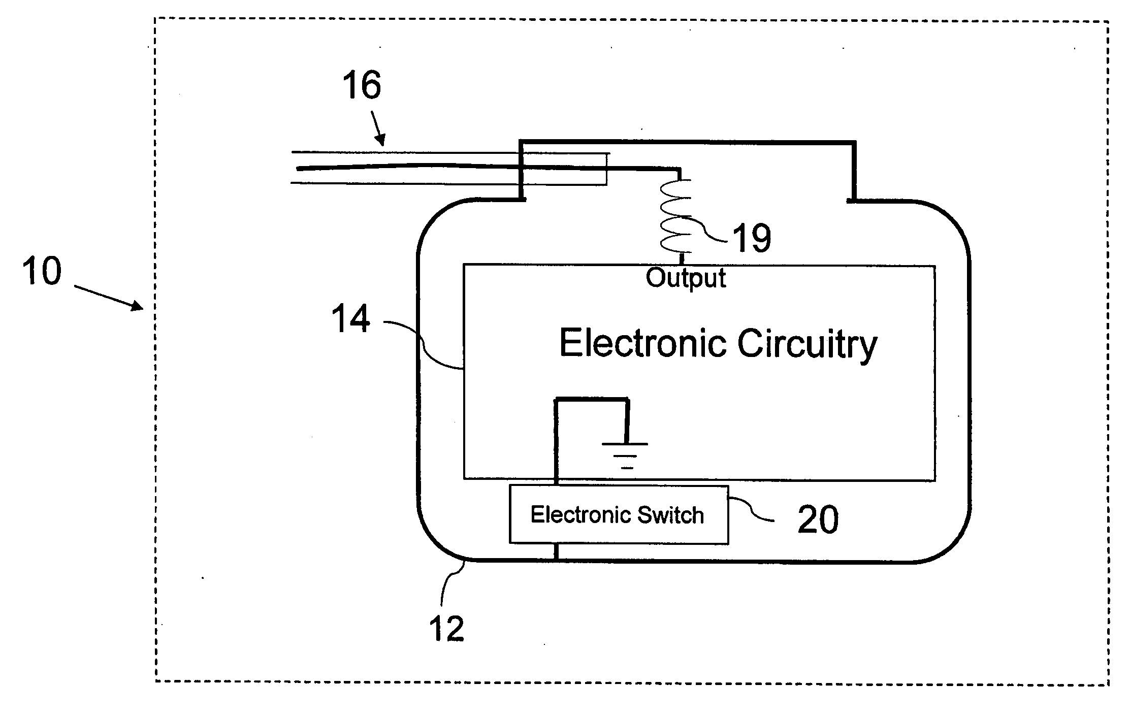
[0145]With the purpose of testing the CSC circuit, a circuit was designed that resembles an implantable pace generator (IPG). The simple pulse circuit contained a standard 9 Volt battery and a 16F84A 18-pin Enhanced FLASH / EEPROM 8-Bit microcontroller. The 16F84A microcontroller was programmed to generate a 1 msec pulse with a period of 1 sec. A 9 Volt battery and a 16f84A microcontroller were put on the same board and connected to each other. This board was put into a waterproof plastic box having dimensions of 9.5×5×2.5 (cm). Approximately 29 cm copper wires (0.5 mm diameter) were connected to this box for signaling and grounding. The waterproof plastic box was covered by copper tape and this conductive coating was connected to a ground wire.

[0146]In this circuit, a standard resistor value of 27 KΩ was used. A 500 KΩ resistor was connected to a gate of a PMOS transistor in order to have reliable gate control in the experiment. A 10 μF tantalum capacitor and a...


PUM


Abstract

The present invention is directed to a novel implantable lead design which ensures safe magnetic resonance imaging of patients with active metallic implants such as pacemakers, neurostimulators and implantable cardio defibrillators. It is known that radio frequency and gradient fields of the MRI scanners may induce harmful currents on the implant leads. The present invention provides for the use of semiconductor components such as transistors and diodes to prevent such undesired induced currents on the implant leads. Circuits on the implants are designed such that while the induction of currents is prevented, the desired signal transmission in between the implanted pulse generator and the body part is maintained.

Description

CROSS-REFERENCE TO RELATED APPLICATION[0001]This application claims the benefit of U.S. Provisional Application No. 60 / 870,563, filed Dec. 18, 2006, entitled “MRI Compatible Implantable Devices,” which is incorporated herein by reference.BACKGROUND OF THE INVENTION[0002]1. Field of the Invention[0003]The present invention relates to implantable devices, such as, without limitation, pacemakers and, in particular, to mechanisms for resisting the induction of currents in the leads of such devices from an external electromagnetic field and therefore reduce the likelihood of excessive heating from such fields.[0004]2. Description of the Prior Art[0005]Magnetic resonance imaging (MRI) generally is regarded as an extremely safe, non-invasive diagnostic technique. MRI may, however, pose a threat to patients that have implantable devices, such as, without limitation, a deep brain stimulation (DBS) device, a pacemaker, a neurostimulator, or a cardio-defibrillator. Currently, patients with met...

Claims


Application Information

Patent Timeline
Patent Type & Authority Applications(United States)
IPC IPC(8): A61N1/05
CPCA61N1/056A61N2001/086A61N1/3718A61N1/37A61N1/086
Inventor ATALAR, ERGINERMEYDAN, AHMET
Owner ATALAR ERGIN
Why Eureka
Try Eureka