Shield Conductor and Method of Producing Thereof

Inactive Publication Date: 2008-07-03
AUTONETWORKS TECH LTD +2
View PDF9 Cites 14 Cited by
  • Summary
  • Abstract
  • Description
  • Claims
  • Application Information

AI Technical Summary

Benefits of technology

[0018]According to the electric wire of the present invention, since the heat generated in the electric wire is effectively transferred to the pipe via the filler, the electric wire is not only

Problems solved by technology

However, a shield conductor using a pipe is problematic since an air layer exists between the electric wire and the pipe, the heat generated in the electric wire while power is applied is blocked by the air, which has a low heat conductivity, thus becoming less prone to being transferred to the pipe.
Furthermore, since the pipe does not contain an airflow path to outside such as th

Method used


Image

  • Shield Conductor and Method of Producing Thereof
  • Shield Conductor and Method of Producing Thereof
  • Shield Conductor and Method of Producing Thereof

Examples


embodiment 1

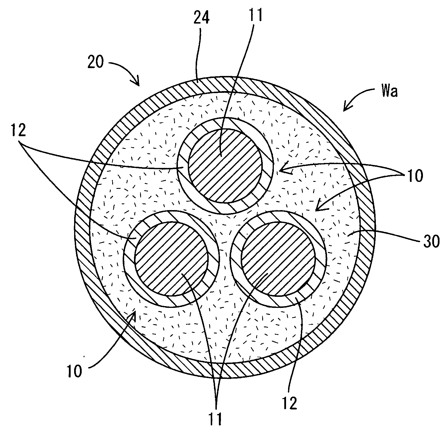
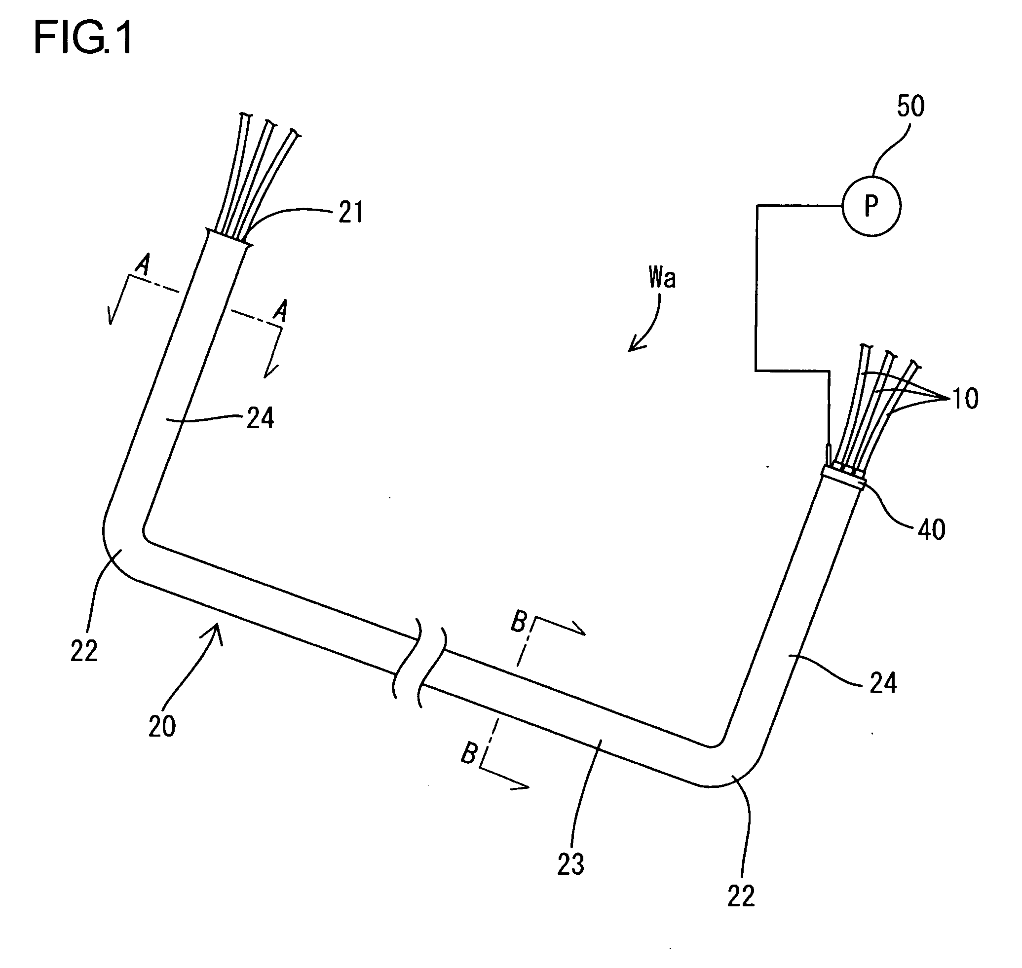
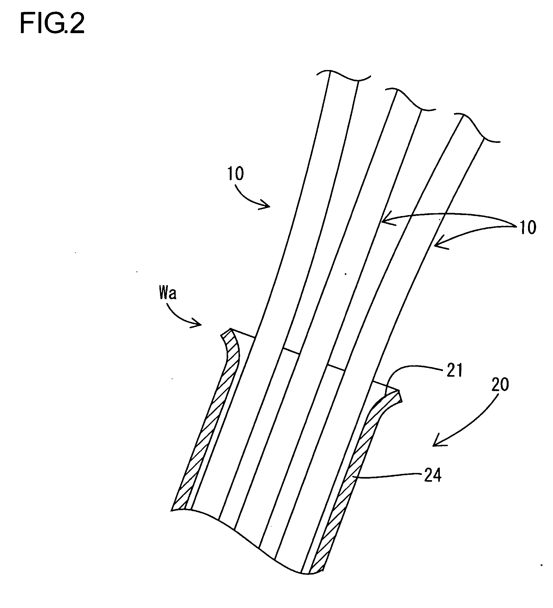
[0040]Hereinafter, embodiment 1 which gives a concrete form of the present invention will be described with reference to FIGS. 1 to 7. The shield conductor Wa of the present embodiment is, for example, one disposed among apparatuses (not shown) constituting a drive power source in an electric vehicle, such as a battery, an inverter, and a motor. It is configured such that three non-shield type electric wires 10 are inserted into a pipe 20 which has both the function of electromagnetically shielding the three non-shield type wires 10 as a whole, and the function of protecting the electric wire from an impact from the outside such as a rebounding stone.

[0041]The electric wire 10 is in a form in which the outer periphery of a conductor 11 made of a metal (such as, for example, an aluminum alloy, a copper alloy, etc.) is enclosed by an insulation coating 12 made of a synthetic resin; and the conductor 11 is comprised of a twisted wire formed by weaving multiple thin wires (not shown) in...

embodiment 2

[0063]Next, the shield conductor Wc according to the embodiment 2 will be described with reference to FIGS. 9 to 14. FIG. 9 is a schematic side sectional view to exemplify the shield conductor Wc according to embodiment 2, and FIG. 10 is a sectional view taken along the line C-C of FIG. 9. The shield conductor Wc of the present embodiment, which is also wired among apparatuses (not shown) constituting, for example, a drive power source in an electric vehicle, such as a battery, an inverter, and a motor is configured such that three non-shield type electric wires 110 are inserted into a pipe 120 which combines a package shielding function and a electrical-wire protecting function.

[0064]As shown in FIG. 10, the electric wire 110 is formed by baking an insulation coating 112 onto a single core conductor 111 made of a metal (such as an aluminum alloy and a copper alloy), and is configured as, for example, an enameled wire. The cross-sectional profile of the electric wire 110 is configur...


PUM

PropertyMeasurementUnit
Electrical conductivityaaaaaaaaaa
Heataaaaaaaaaa

Abstract

Since it is configured such that the gap between the pipe 20 and the electric wire 10 in the pipe 20 is filled with a filler 30 having a heat conductivity higher than that of air, the heat generated in the electric wire 10 is transferred to the filler 30, then from the filler 30 to the pipe 20, and is discharged from the outer periphery of the pipe 20 to the outside air. Since the filler 30 has a heat conductivity higher than that of air, the performance in discharging the heat generated in the electric wire 10 is superior compared with a case in which the filler 30 is not charged. Thus, heat dissipation in the shield conductor using a pipe is improved.

Description

TECHNICAL FIELD[0001]The present invention relates to a shield conductor and a method of producing thereof.BACKGROUND ART[0002]For example, in an electric vehicle or a hybrid vehicle, it is necessary to use a shield conductor as power supply lines to an inverter apparatus, and from the inverter apparatus to a drive motor. As the shield conductor used in such applications, there has been considered a structure in which a plurality of non-shield electric wires are enclosed with a shield member formed of a tubular braided wire, which is formed by weaving a thin metal wire into a mesh form, to electromagnetically shield them in a package.[0003]However, in a vehicle, not only electromagnetic shielding of conductor lines, but also the protection of the electric wires (such as protection from rebounding stones during driving) needs to be considered since those shield conductors are wired on the bottom face of a vehicle body as well as in an engine room. For this reason, generally, a config...

Claims


Application Information

Patent Timeline
IPC IPC(8): H02G3/00H01R43/00
CPCH01B7/16Y10T29/53243H01B7/428
Inventor WATANABE, KUNIHIKO
Owner AUTONETWORKS TECH LTD
Why Eureka
Try Eureka