DC power plane structure

a power plane and direct current technology, applied in the direction of cross-talk/noise/interference reduction, electrical apparatus construction details, non-printed electric components association of printed circuits, etc., can solve the problems of large increase in manufacturing costs, inconvenience in wiring layout of circuit boards, and negative affecting signal transmission quality. , to achieve the effect of reducing the use of a large number of capacitors in the conventional art, and high manufacturing costs

Inactive Publication Date: 2008-07-03
INVENTEC CORP
View PDF13 Cites 36 Cited by
  • Summary
  • Abstract
  • Description
  • Claims
  • Application Information

AI Technical Summary

Benefits of technology

[0010]In view of the above problems, it is a main object of the present invention to provide a power plane structure for inhibiting high-frequency noise, so as to solve the problems existing in the prior art that the method of partitioning the power plane can only inhibit low-frequency noise o...

Problems solved by technology

However, as the signal transmission frequency becomes higher, noise is generated between a power plane and a ground plane in the multi-layer printed circuit board, which negatively affects the signal transmission quality.
When quickly switching signals of an integrated circuit (IC) in the high-frequency digital circuit, a transient voltage difference is generated in the power plane, thus causing noise.
However, in the above designs, resonance noises of certain frequencies still exist, which cause inconvenience in the layout of wirings on the circuit board.
Thus, t...

Method used


Image

  • DC power plane structure
  • DC power plane structure
  • DC power plane structure

Examples


Embodiment Construction

[0021]The purpose, construction, characteristics, and functions of the present invention are further described accompanied with the embodiments below.

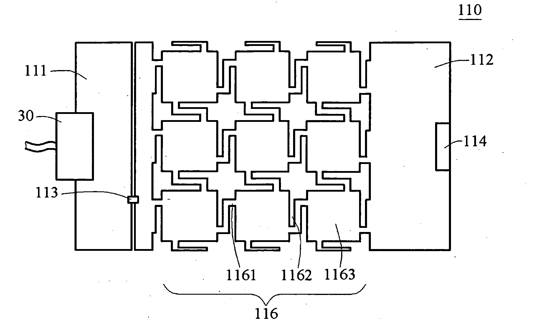
[0022]First, referring to FIG. 3, a top view of the first embodiment of the present invention is shown. As shown in FIG. 3, a power plane 110 has a DC power 30, and an I / O port 114 for connecting a transmission line so that the power plane 110 is connected with another circuit board to transmit or receive a signal. The power plane 110 is partitioned into two parts, namely a first circuit area 111 and a second circuit area 112 which are electrically connected through a noise filter 113, and a band gap structure 116 is formed on the second circuit area 112.

[0023]A band gap structure 116, for example, an electromagnetic band gap (EBG) structure or a photonic band gap (PBG) structure is formed on the second circuit area 112, so as to make one end of the noise filter 113 electrically connected to the DC power output end of the first circu...


PUM


Abstract

A DC power plane structure applied in multi-layer circuit board is provided. The DC power plane structure includes a first circuit area for receiving a DC power, a noise filter with one end electrically connected to a DC power output end of the first circuit area, and a second circuit area which is electrically isolated from the first circuit area. The second circuit area has a band gap structure, and the DC power input end of the band gap structure is electrically connected to the other end of the noise filter for inhibiting high-frequency noise generated between layers of the multi-layer circuit board.

Description

BACKGROUND OF THE INVENTION[0001]1. Field of Invention[0002]The present invention relates to a direct current (DC) power plane structure, and more particularly to a DC power plane structure for inhibiting noise between layers of a multi-layer circuit board.[0003]2. Related Art[0004]Recently, as the mass are increasingly demanding for higher information transmission speed, the frequency of signal transmission becomes higher and higher. Thus, a high-frequency digital circuit design becomes a main development field of circuit design towards higher speed, compacted volume, and low voltage. Due to the demand for a design with small volume, multi-layer printed circuit boards have been widely applied in the circuit design. However, as the signal transmission frequency becomes higher, noise is generated between a power plane and a ground plane in the multi-layer printed circuit board, which negatively affects the signal transmission quality. Accordingly, how to inhibit noise transmitted alo...

Claims


Application Information

Patent Timeline
IPC IPC(8): H05K1/16H05K1/00
CPCH05K1/0231H05K1/0236H05K2201/09972H05K2201/09663H05K2201/09681H05K1/165
Inventor CHEN, YEN-HAOLAI, CHUN-YU
Owner INVENTEC CORP
Why Eureka
Try Eureka