

Composite membrane for separation of carbon dioxide
- Summary
- Abstract
- Description
- Claims
- Application Information
AI Technical Summary
Benefits of technology
Problems solved by technology
Method used
Image

Examples
example 1
[0045]A composite membrane was prepared by using two extended polytetrafluoroethylene (ePTFE) membranes from BHA Technologies and hydroxyl-terminated polydimethylsiloxane (PDMS) obtained from Gelest® having a viscosity of about 90-120 cSt. The PDMS was crosslinked with an equimolar mixture of N-propyl silicate and dibutyl tin oxide. PDMS was mixed with the N-propyl silicate and the dibutyl tin oxide in polymer cups and mixed by hand.
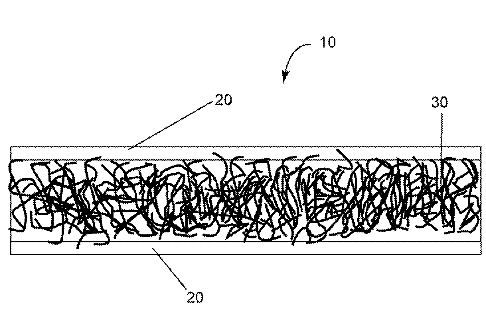
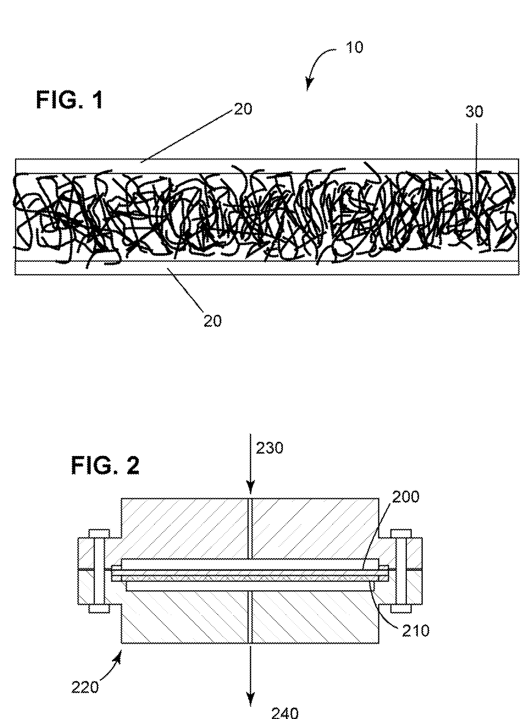
[0046]Two heavy glass slabs were used as support for the e-PTFE membranes. One e-PTFE membrane was wrapped snug on a glass slab. Four spacers of 0.5 mm thickness were placed on the wrapped e-PTFE membrane to control the thickness of the PDMS layer. The PDMS crosslinking mixture was poured on to the wrapped e-PTFE membrane at a thickness of 500 microns The other glass slab with the wrapped membrane was placed on top of the spacer after the PDMS slurry was poured onto the lower glass slab. The upper glass slab was lifted off a few minutes later. The membra...
example 2
[0052]A composite membrane was prepared by using two extended polytetrafluoroethylene (ePTFE) membranes from BHA Technologies and hydroxyl-terminated polydimethylsiloxane (PDMS) obtained from Gelest® having a viscosity of about 500,000 cSt. The PDMS was crosslinked with an equimolar mixture of N-propyl silicate and dibutyl-tin-oxide. PDMS was mixed with the N-propyl silicate and the dibutyl tin oxide in polymer cups and mixed by hand.
[0053]Two heavy glass slabs were used as support for the e-PTFE membranes. One e-PTFE membrane was wrapped snug on a glass slab. Four spacers of 0.5 mm thickness were placed on the wrapped e-PTFE membrane to control the thickness of the PDMS layer. The crosslinking mixture PDMS was poured on to the wrapped e-PTFE membrane at a thickness of the 500 microns. The other glass slab with the wrapped membrane was placed on top of the spacer after the PDMS slurry was poured onto the lower glass slab. The upper glass slab was lifted off a few minutes later. The ...
example 3
[0056]A composite membrane was prepared by using two extended polytetrafluoroethylene (ePTFE) membranes from BHA Technologies and hydroxyl-terminated polydimethylsiloxane (PDMS) obtained from Gelest® having a viscosity of about 90-120 cSt. The PDMS was crosslinked with an equimolar mixture of N-propyl silicate and dibutyl-tin-oxide. PDMS was mixed with the N-propyl silicate and the dibutyl tin oxide in polymer cups and mixed by hand. This is mixed with 11.8 g of beta-Zeolite. A uniform slurry mixture was formed using a planetary mixer.
[0057]Two heavy glass slabs were used as support for the e-PTFE membranes. One e-PTFE membrane was wrapped snug on a glass slab. Four spacers of 0.5 mm thickness were placed on the wrapped e-PTFE membrane to control the thickness of the slurry mixture layer. The slurry mixture was poured onto the wrapped e-PTFE membrane at a thickness of 500 microns. The other glass slab with the wrapped membrane was placed on top of the spacer after the slurry mixture...
PUM
| Property | Measurement | Unit |
|---|---|---|
| Thickness | aaaaa | aaaaa |
| Thickness | aaaaa | aaaaa |
| Thickness | aaaaa | aaaaa |
Abstract
Description
Claims
Application Information