

Desalination system
- Summary
- Abstract
- Description
- Claims
- Application Information
AI Technical Summary
Benefits of technology
Problems solved by technology
Method used
Image

Examples
Embodiment Construction
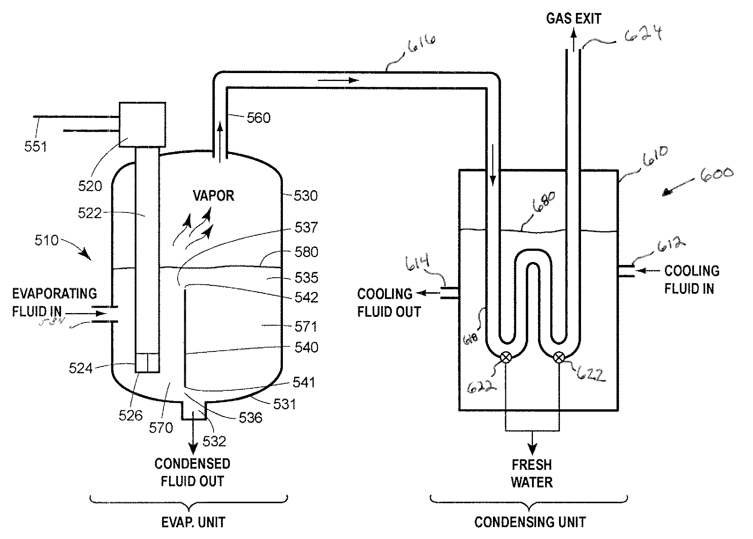
[0023]The performance of desalination systems according to the disclosure depends on the moisture content and temperature of the gas and the thermodynamic properties of the evaporative fluid, which are usually ambient air and water. As with conventional desalination systems, equations developed by Merkel that are based the enthalpy potential difference between the evaporative fluid and air, may be used to closely define the performance of a desalination system that is constructed according to the invention for a particular application. Desalination systems according to the disclosure can be substituted for conventional desalination systems. Conventional means of controlling the flow of evaporative fluid through the desalination system may be employed. Likewise, conventional means of controlling desalination systems to meet the requirements of a particular desalination system application may be employed. Multiple desalination systems according to the invention may be connected in ser...
PUM
| Property | Measurement | Unit |
|---|---|---|
| Volume | aaaaa | aaaaa |
| Area | aaaaa | aaaaa |
| Area | aaaaa | aaaaa |
Abstract
Description
Claims
Application Information