Electrochemical mechanical polishing apparatus conditioning method, and conditioning solution

a technology of electrochemical mechanical polishing and conditioning solution, which is applied in the direction of abrasive surface conditioning devices, manufacturing tools, and lapping machines, etc., can solve the problems of large drop in polishing rate, large change in polishing rate in response, and high cost of power supply units (power sources) adapted to apply voltage to electrodes concentrically facing the wafer, so as to achieve uniform polishing rate, easy to perform workpiece polishing, and low cost

Inactive Publication Date: 2008-08-07
EBARA CORP
View PDF3 Cites 53 Cited by
  • Summary
  • Abstract
  • Description
  • Claims
  • Application Information

AI Technical Summary

Benefits of technology

[0026]The present invention has been made in view of the above drawbacks. It is a first object of the present invention to provide an electrochemical mechanical polishing apparatus which does not have plural electrodes, can thus lower a cost, and can easily perform polishing of a workpiece, such as a wafer, in a low-polishing-pressure area at a high speed with a uniform polishing rate being secured within a surface of the workpiece in its entirety.

Problems solved by technology

Introduction of the Low-k material, on the other hand, raises an issue of how to reduce damages to the Low-k material including destruction and removal of the Low-k material during the polishing process.
This fact raises problems including: (1) a large drop in polishing rate; and (2) a large change in polishing rate in response to a small change in polishing pressure.
However, the power supply units (power sources), which are adapted to apply the voltage to the electrodes concentrically facing the wafer, are generally expensive.
Moreover, an increased number of power sources incur not only an increased cost, but also complicated control mechanism.
However, when the electric supply contact, made from metal, is brought into direct contact with the conductive film, such as a copper film, so as to supply the electric current to the conductive film using a polishing pad made from an insulating material, a portion of the surface of the conductive film contacting the electric supply contact would be damaged.
Such a damaged portion cannot be used as a semiconductor device.
Furthermore, a contact area between the conductive film and the electric supply contact is relatively small, and therefore a stable contact therebetween cannot be secured.
As a result, it would become difficult to reliably supply the electric current from the electric supply contact to the conductive film.
Therefore, it is generally difficult to use the stationary joint mechanism for supplying the electric current to the polishing pad.
Consequently, a voltage drop would occur in the polishing pad due to a relatively large electrical resistance, thus causing variations in electric potential within the surface of the conductive film.
Such variations in electric potential result in variations in polishing rate within the surface of the conductive film.
Therefore, the electrochemical reaction would be rendered unstable, and stable supply of current cannot be secured.
Further, in this current-supply method, a large amount of electric current flows between the retainer ring and the cathode, thus lowering a current efficiency during polishing.
However, in this method, an actual contact area of a current supply point is relatively small, and this current supply point is limited to a periphery of the substrate.
As a result, it is generally difficult to uniformly supply the current over a surface of the substrate.
Use of the pad having an electrical conductivity entails problems other than the way of current supply.
Such oxygen, produced on the surface of the polishing pad, would cause production of pits on a surface of copper, and would lower a polishing rate of copper.
Further, the above-described rotary type requires a large amount of electrolytic solution, because the apparatus of this type is designed to supply the electrolytic solution from above the polishing pad while rotating the polishing table.
In the electrochemical mechanical polishing, the electrolytic solution is expendable, but expensive.
If the polishing process is continued with the by-products being left on the processing electrode, an electrical resistance between a substrate and the processing electrode would be changed, thus adversely affecting control of the polishing rate within a surface of the substrate.
However, it is difficult to remove the by-products deposited on the surface of the processing electrode, which is covered with the polishing pad, by washing the processing electrode with the cleaning liquid, e.g., pure water.
As a result, components of the etching liquid, remaining on the surface of the processing electrode after conditioning, would affect the polishing process.

Method used


Image

  • Electrochemical mechanical polishing apparatus conditioning method, and conditioning solution
  • Electrochemical mechanical polishing apparatus conditioning method, and conditioning solution
  • Electrochemical mechanical polishing apparatus conditioning method, and conditioning solution

Examples


example 1

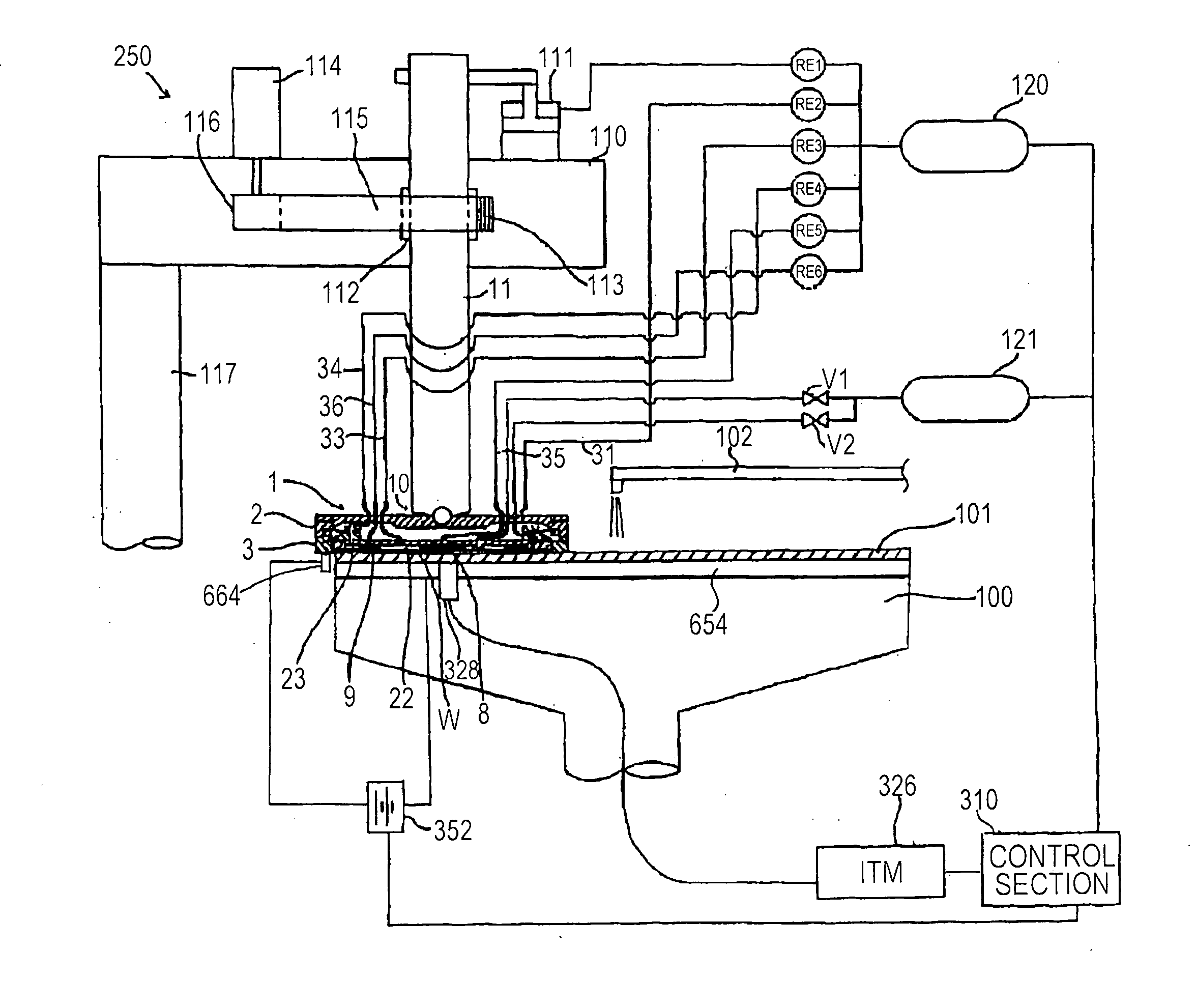
[0341]An electrolytic solution containing malonic acid, methanesulfonic acid, and benzotriazole (corrosion inhibitor) as main components, and polyacrylic acid (molecular weight: 5000), methanol, a surfactant, and abrasive particles as additives was prepared. A conditioning solution containing malonic acid, methanesulfonic acid, and hydrogen peroxide (H2O2) was prepared. Using the electrochemical mechanical apparatus shown in FIGS. 44 and 45, conditioning was performed as follows. While the processing table 710 was rotated at a rotational speed of 30 rpm, the conditioning solution was supplied to the upper surface of the processing table 710 at a flow rate of 200 ml / min to perform conditioning of the processing electrode 716 and the polishing pad 718 for two minutes.

[0342]Next, while the processing table 710 was rotated at a rotational speed of 60 rpm, ultrapure water was supplied to the upper surface of the processing table 710 at a flow rate of 200 ml / min to perform rinsing of the ...


PUM

PropertyMeasurementUnit
resistanceaaaaaaaaaa
relative speedaaaaaaaaaa
pressureaaaaaaaaaa

Abstract

An electrochemical mechanical polishing apparatus is for use in polishing of a conductive material (e.g., metal) on a surface of a substrate by combination of electrochemical action and mechanical action. This apparatus includes a polishing table having divided electrodes and adapted to hold a polishing pad having a polishing surface, a polishing head adapted to hold a workpiece having a conductive film and to press the workpiece against the polishing surface, a second electrode for supplying an electric current to the conductive film, an electrolytic-solution supply section for supplying an electrolytic solution to the polishing surface, a detecting section adapted to detect a signal corresponding to a thickness of the conductive film, a variable resistance unit having the same number of variable resistors as the number of divided electrodes, a moving mechanism for providing relative movement between the workpiece and the polishing surface, and a control section adapted to control each of the variable resistors based on the signal from the detecting section.

Description

BACKGROUND OF THE INVENTION[0001]1. Field of the Invention[0002]The present invention relates to an electrochemical mechanical polishing apparatus, and more particularly to an electrochemical mechanical polishing apparatus for use in polishing of a conductive material (e.g., metal), formed on a surface of a substrate such as a semiconductor wafer, by combination of electrochemical action and mechanical action.[0003]The present invention also relates to a method of conditioning a processing electrode provided in an electrochemical mechanical polishing apparatus which is for performing electrochemical mechanical polishing of a conductive material of a workpiece. The present invention also relates to a conditioning solution for use in such a conditioning method. The electrochemical mechanical polishing apparatus is used to polish a conductive film, formed on a surface of a substrate of electronic device, such as a semiconductor device and a display, and to polish a metal of, for exampl...

Claims


Application Information

Patent Timeline
Patent Type & Authority Applications(United States)
IPC IPC(8): B24B49/00B24B37/04
CPCB23H5/08B24B37/042B24B37/046H01L21/7684B24B53/017H01L21/32125B24B49/10
Inventor KOBATA, ITSUKITOMA, YASUSHIKODERA, AKIRASUZUKI, TSUKURUMAKITA, YUJISAITO, TAKAYUKI
Owner EBARA CORP
Why Eureka
Try Eureka