Wave Absorber and Manufacturing Method of Wave Absorber

a manufacturing method and technology of absorber, applied in the direction of printed circuit manufacturing, conductive pattern formation, radiating element structural forms, etc., can solve the problems of increased weight, fluctuation of absorption properties, and increased thickness, and achieve effective absorption of em waves, high reflection attenuation properties, and sufficient reflection attenuation performance

Inactive Publication Date: 2008-09-04
MITSUBISHI GAS CHEM CO INC
View PDF21 Cites 17 Cited by
  • Summary
  • Abstract
  • Description
  • Claims
  • Application Information

AI Technical Summary

Benefits of technology

[0101]In addition, with the wave absorber of the present invention, it is possible to provide an open stub (e.g., a linear pattern) on a portion of the aforementioned patterns. By adjusting the size, form, or disposition of said open stub (e.g., linear pattern), the wave absorber of the present invention is able to conduct adjustment to a frequency (wavelength) and bandwidth with high reflection attenuation properties.
[0102]Accordingly, the present invention is able to offer a wave absorber capable of effectively absorbing the EM

Problems solved by technology

However, with respect to wave absorbers where magnetic powder such as ferrite or soft magnetic metal is mixed and dispersed in an insulating matrix such as rubber or plastic, and molded and processed as recorded in Patent Literature 1, it is possible to form a relatively thin absorber, but there are the drawbacks that a more thickness is necessary when high-performance wave absorption is required, and that weight increases due to use of material of high specific gravity.
Next, with respect to wave absorbers where polyurethane foam or the like is impregnated with dielectric loss powder such as carbon black, and processed as recorded in Patent Literature 2, there is the drawback that i

Method used


Image

  • Wave Absorber and Manufacturing Method of Wave Absorber
  • Wave Absorber and Manufacturing Method of Wave Absorber
  • Wave Absorber and Manufacturing Method of Wave Absorber

Examples


first embodiment

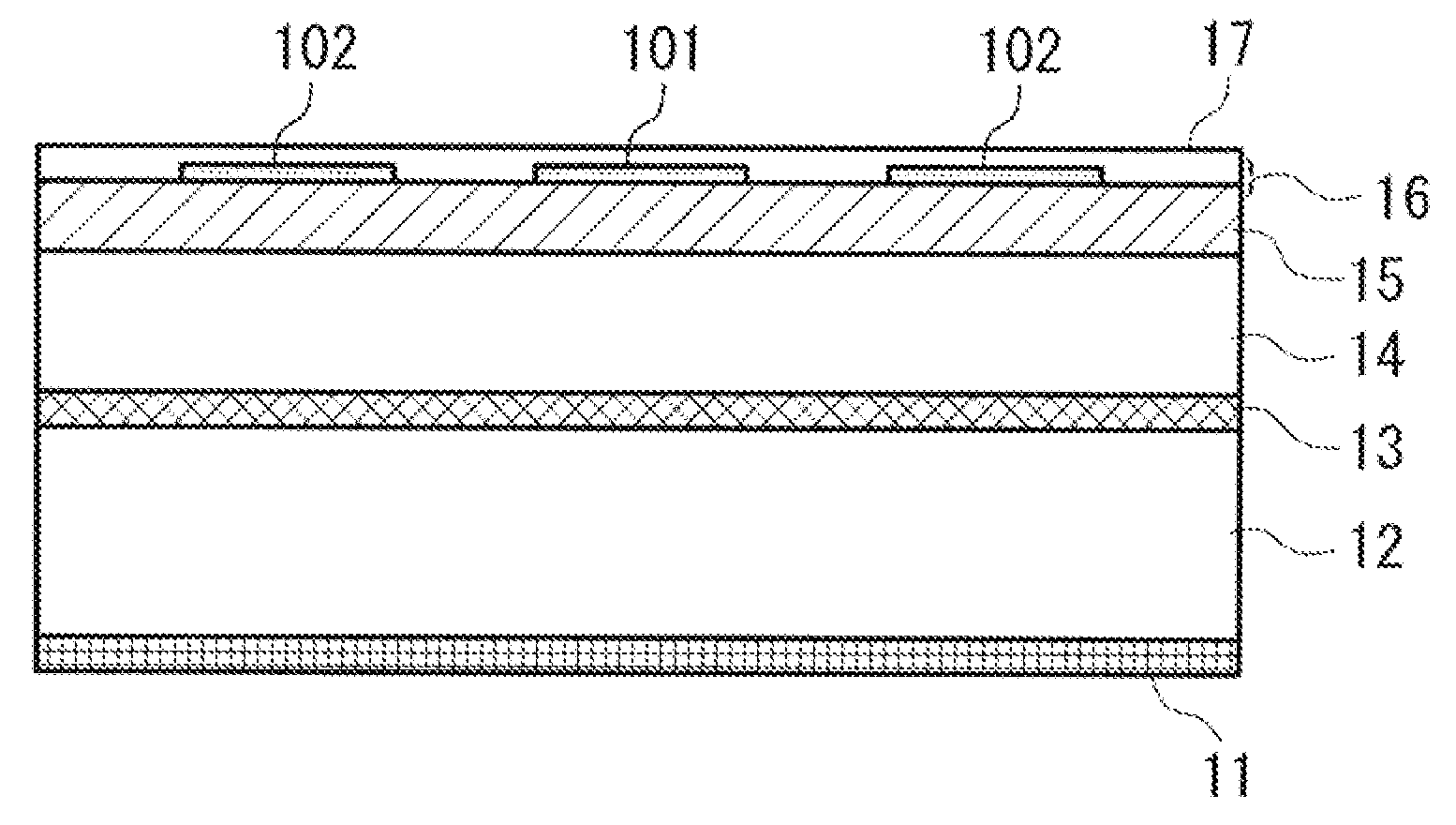
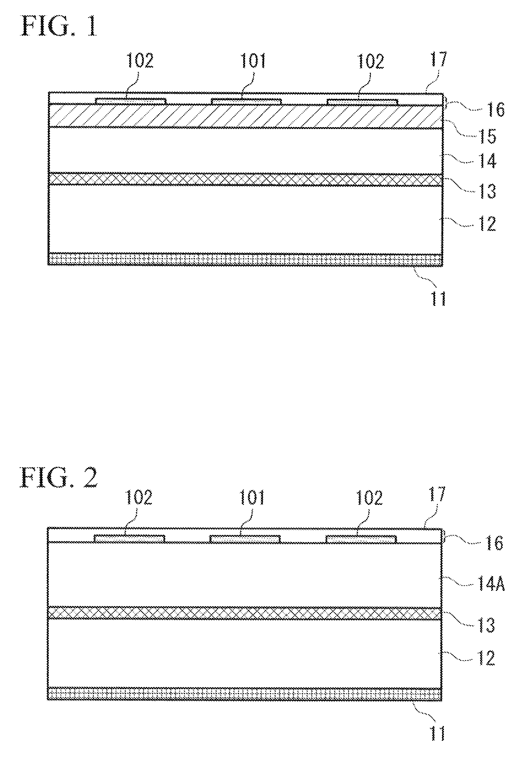
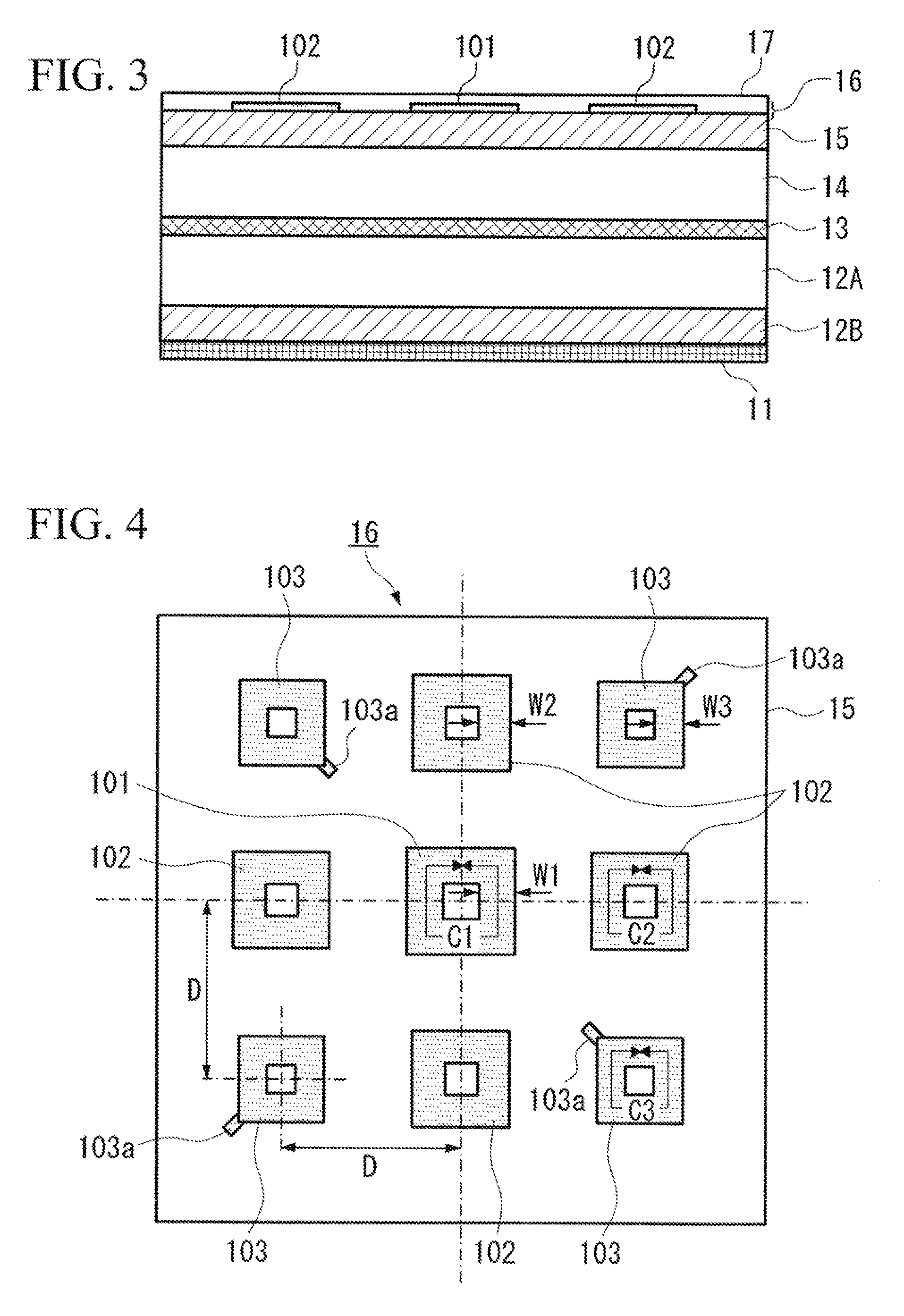
[0221]FIG. 1 is a sectional drawing showing the schematic configuration of a wave absorber which is a first embodiment of the present invention. The wave absorber of the present embodiment is configured by sequential lamination of a grid-like conductor layer 11 formed by copper foil (i.e. an electric conductor) of 12 μm thickness, a polycarbonate substrate 12 of 1.7 mm thickness constituting a first dielectric layer, a high-resistance conductor layer 13 having a surface resistance value (sheet resistance value) of 400Ω / □, a laminate of a polycarbonate substrate 14 of 1.3 mm thickness constituting a second dielectric layer A and a BT (bismaleimide-triazine) substrate 15 of 0.3 mm thickness constituting a second dielectric layer B, a pattern layer 16 where multiple loop patterns of differing shape formed by copper foil of 12 μm thickness are cyclically disposed, and PET (polyethylene terephthalate) 17 with of 0.1 mm thickness that serves as a protective layer. Here, the grid-like cond...

second embodiment

[0231]FIG. 6 is a sectional view showing the schematic configuration of a wave absorber, which is a second embodiment of the present invention. The wave absorber of the present embodiment is configured by sequential lamination of a grid-like conductor layer 21 formed by copper foil (i.e. an electric conductor) of 12 μm thickness, a polycarbonate substrate 22 of 1.5 mm thickness constituting a first dielectric layer, a high-resistance conductor layer 23 having a surface resistance value (sheet resistance value) of 400Ω / □, a laminate of a polycarbonate substrate 24 of 1.1 mm thickness constituting a second dielectric layer A and a BT (bismaleimide-triazine) substrate 25 of 0.3 mm thickness constituting a second dielectric layer B, and a pattern layer 26 where multiple loop patterns of differing shape formed by copper foil of 12 μm thickness are cyclically disposed. Here, the grid-like conductor layer 21 and the high-resistance conductor layer 23 are identical to the grid-like conducto...

third embodiment

[0235]FIG. 9 is a sectional view showing the schematic configuration of a wave absorber, which is a third embodiment of the present invention. The wave absorber of the present embodiment is configured by sequential lamination of a conduct layer 31 formed by copper foil (i.e. an electric conductor) of 12 μm thickness, a polycarbonate substrate 32 of 0.7 mm thickness constituting a first dielectric layer, a polypropylene substrate 33 of 1.3 mm thickness where 20 weight parts of carbon powder constituting a dielectric loss layer are dispersed, and made to foam 3.8-fold, a laminate of a polycarbonate substrate 34 of 0.4 mm thickness constituting a second dielectric layer A and a BT (bismaleimide-triazine) substrate 35 of 0.3 mm thickness constituting a second dielectric layer B, and a pattern layer 36 where multiple loop patterns of differing shape formed by copper foil of 12 μm thickness are cyclically disposed. Here, as a carbon-dispersed foam substrate is used as the dielectric loss ...


PUM

PropertyMeasurementUnit
Fractionaaaaaaaaaa
Fractionaaaaaaaaaa
Fractionaaaaaaaaaa

Abstract

The problem of the present invention is to offer a wave absorber that has reflection attenuation capability sufficient to enable prevention of communication disturbances due to reflection and the like of EM waves, that enables greater thinness and lighter weight, and that has wide-band attenuation properties, as well as a manufacturing method of the wave absorber. The wave absorber of the present invention has a structure which sequentially laminates a grid-like conductor layer composed of an electric conductor, a first dielectric layer, a high-resistance conductor layer having a surface resistivity within a prescribed range, a second dielectric layer, and a pattern layer having multiple patterns composed of an electric conductor, wherein each pattern in said pattern layer differs in either or both of size and form relative to another adjacent pattern.

Description

BACKGROUND OF THE INVENTION[0001]1. Field of the Invention[0002]The present invention relates to a wave absorber and a wave absorber manufacturing method. In addition, the present invention relates to a wave absorber that enables prevention of communication disturbances from reflection and the like of electromagnetic (EM) waves and that enables a thinner and more lightweight product, and to a wave absorber manufacturing method.[0003]This application claims priority from Japanese Patent Application No. 2004-55051 filed on Feb. 27, 2004, Japanese Patent Application No. 2004-265233 filed on Sep. 13, 2004, and Japanese Patent Application No. 2004-371225 filed on Dec. 22, 2004, the contents of which are incorporated herein by reference.[0004]2. Description of Related Art[0005]Due to the development of cell phones, wireless LAN (Local Area Networks), ITS (Intelligent Transport Systems) and the like in recent years, it has become necessary to protect communicated information and to prevent...

Claims


Application Information

Patent Timeline
IPC IPC(8): H05K9/00H01Q17/00H05K3/10H05K3/46H01Q1/38H01Q1/44H01Q15/00
CPCH01Q1/38H01Q1/44H01Q15/00H01Q17/00Y10T29/49126H05K9/0086H05K9/0088H01Q15/0013H05K9/0083H05K9/00
Inventor MASUDA, YOSHIYUKIOTANI, NOBORUNAKANO, HISAMATSU
Owner MITSUBISHI GAS CHEM CO INC
Why Eureka
Try Eureka