Method and apparatus for internal hydration of a fuel cell system

a fuel cell and internal hydration technology, applied in the field of fuel cell systems, can solve the problems of affecting reducing the efficiency of the fuel cell system, so as to achieve the effect of substantially reducing the dry-out of the cathod

Inactive Publication Date: 2008-09-11
MTI MICROFUEL CELLS
View PDF15 Cites 12 Cited by
  • Summary
  • Abstract
  • Description
  • Claims
  • Application Information

AI Technical Summary

Benefits of technology

[0016]These and other disadvantages of prior techniques are overcome by the present invention in which an enthalpy exchanger is thermally integrated into a fuel cell. As used herein, “enthalpy” includes heat and moisture in a flow stream, typically generated in one of the reactions in the fuel cell core. In one embodiment, the incoming oxidant reactant is an inlet air stream that is directed into an inlet manifold. The incoming air stream is directed in a substantially counter flowing manner with an outgoing exhaust which travels in an exhaust manifold leading from the cathode of the fuel cell. The inlet manifold and the outlet manifold are separated by an enthalpy exchange element which may be a water permeable membrane that resists the flow of gas there through, but collects moisture from the exhaust and allows the moisture to be picked up by the passing inlet stream, thus humidifying the stream before it enters the cathode. By introducing humid air, rather than dry air, cathode dry-out is substantially reduced. The effects are further enhanced by a water pushback technique in which water is directed across the cell electrolyte from cathode to anode for the anodic reaction of the fuel cell. In a preferred embodiment, the enthalpy exchanger is a two layer structure that is folded onto the fuel cell so that it aligns with the “footprint” of the fuel cell.

Problems solved by technology

Reformer based systems are not generally considered a viable power source for small devices due to size and technical complexity of present fuel reformers.
Many fuel cell systems are run at approximately room temperature, however, in order to obtain an adequate power output and maintain efficiency, such fuel cells are heavily catalyzed, which requires significant amounts of precious metal such as platinum.
The cost of platinum has sharply increased in recent years.
However, the water needed to keep the membrane hydrated and the water needed for the anodic reaction can vaporize and thus is lost from the reaction zone at such higher temperatures.
On the other hand, excessive hydration must be avoided to prevent flooding of the cathode with liquid water, which could restrict oxygen access to the cathode reaction site.
However, these prior techniques for recycling effluent water have required undesirably large or complex support devices external to the fuel cell itself, increasing cost, size and depriving the system of useful power density due to parasitic losses.
These prior means require either management of liquid water or use of add-on equipment external to the fuel cell structure; adding cost, size, and risk of operating failure.
Alternatively, one can operate the fuel cell at a lower temperature and sacrifice power output of the fuel cell, especially in high ambient temperatures.
Such retrofitted components add cost, size and complexity and increases the risk of operating failure of the fuel cell system.

Method used


Image

  • Method and apparatus for internal hydration of a fuel cell system
  • Method and apparatus for internal hydration of a fuel cell system
  • Method and apparatus for internal hydration of a fuel cell system

Examples


example

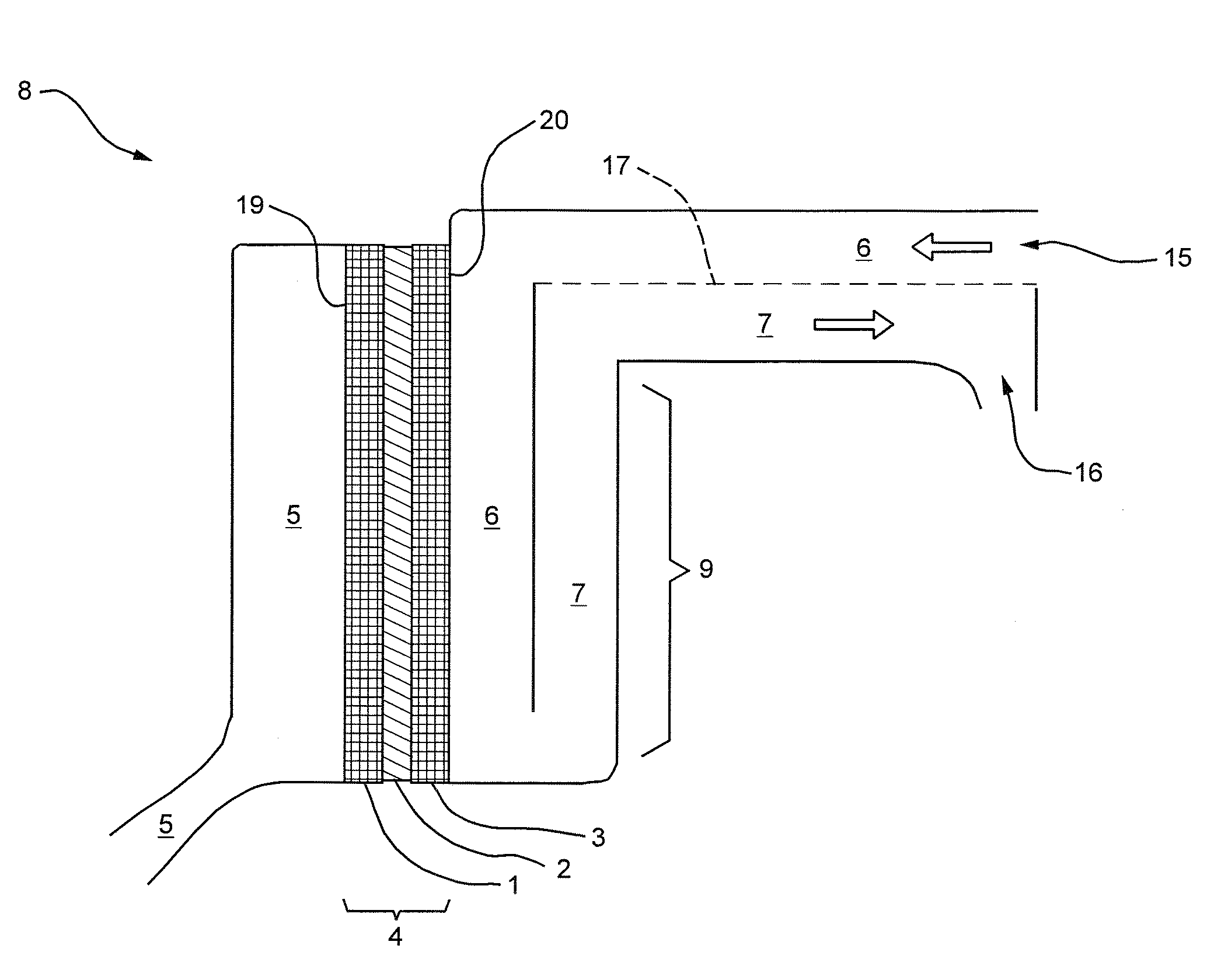
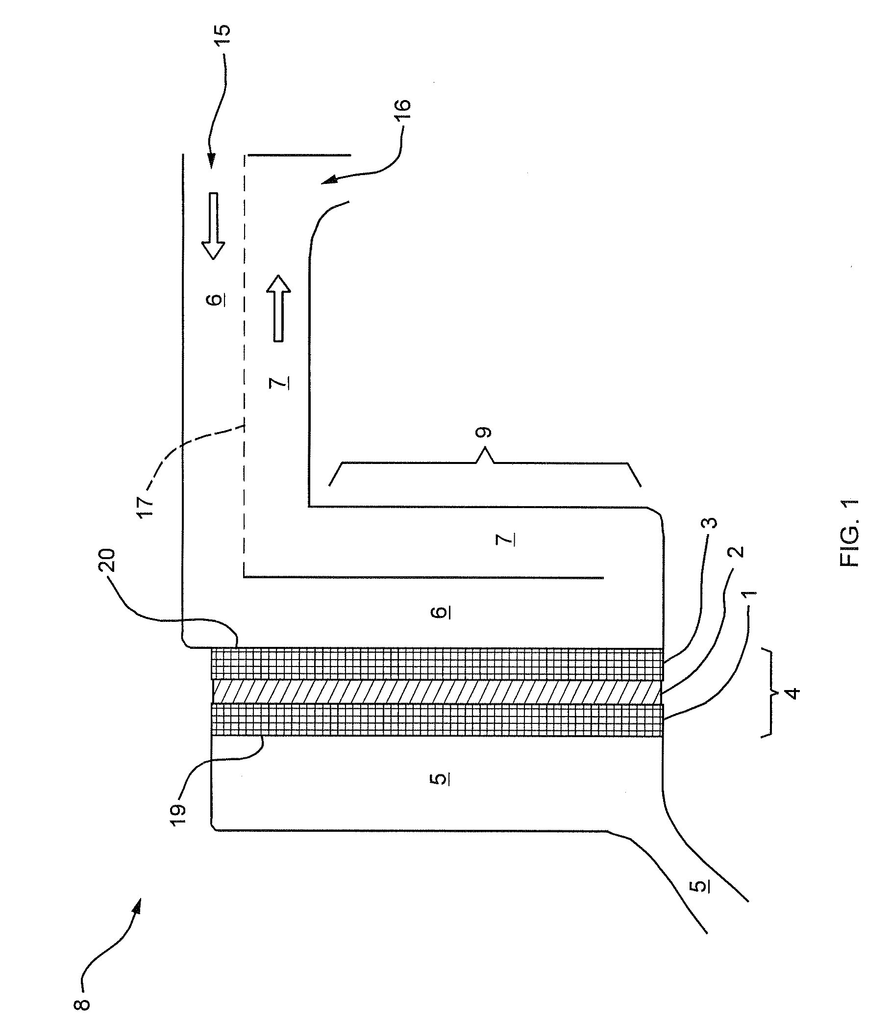
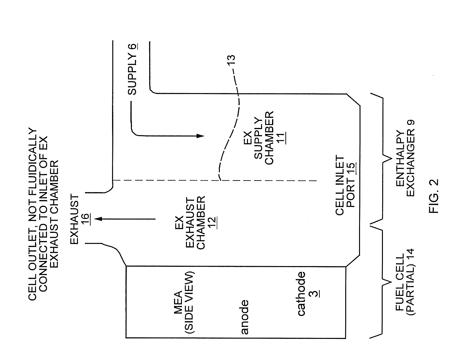
[0039]The embodiment of the present invention illustrated in FIG. 4 was tested and the test was performed using a fuel cell with about 12 square centimeters of cell area. The operation comprised an anode flow of about 0.5 milliliters per minute of methanol and about 0.7 cubic centimeters of air on the cathode side. The dimensions of the inlet 5 measured perpendicular to the cell area or left to right in the figure was about 0.03 inches. The protonically conductive layer plus diffusion layers was about 0.025 inches thick including a protonically conductive of 0.001 to 0.005 inches thick. The exhaust chamber 12 and supply chamber 11 were each about 0.03 inches wide in diameter. The cathode flow was present at the air inlet 6 at a pressure of about 0.3 psi. The fuel cell was run at a temperature of 80° C. This produced power output capacity of about 50 milliwatts per square centimeter of cell area.

[0040]It should be further noted that the air inlet supply and exhaust will be enhanced u...


PUM

PropertyMeasurementUnit
protonically conductiveaaaaaaaaaa
enthalpyaaaaaaaaaa
volumeaaaaaaaaaa

Abstract

A fuel cell system having internal pushback of water, with a compact, thermally integrated enthalpy exchanger enabling effective hydration control in a small fuel cell system is provided. The enthalpy exchanger provides for the moisture in the fuel cell effluent to by used to humidify the incoming air stream to allow the fuel cell to be operated at higher temperatures while avoiding dry out. The enthalpy exchanger includes a moisture permeable membrane which collects moisture from the exhaust flow and makes this moisture available to an incoming air stream, thus humidifying the incoming air stream. In addition, the waste heat from the fuel cell reactions is transferred to the incoming air stream. The exhaust stream from the anode can also be used to provide additional moisture and heat to the enthalpy exchanger to be added to the incoming air stream. A water separator is also provided in one embodiment.

Description

BACKGROUND OF THE INVENTION[0001]1. Field of the Invention[0002]This invention relates generally to fuel cell systems, and particularly, to the maintenance of adequate hydration in the fuel cell system.BACKGROUND INFORMATION[0003]Fuel cells are devices in which an electrochemical reaction is used to generate electricity. A variety of materials may be suitable for use as a fuel depending upon the materials that are chosen for the components of the cell and the intended application for which the fuel cell will provide electric power.[0004]Fuel cell systems may be divided into “reformer based” systems (which make up the majority of currently available fuel cells), in which fuel is processed to improve fuel cell system performance before it is introduced into the fuel cell, and “direct oxidation” systems in which the fuel is fed directly into the fuel cell without internal processing.[0005]Because of their ability to provide sustained electrical energy, fuel cells have increasingly been...

Claims


Application Information

Patent Timeline
Patent Type & Authority Applications(United States)
IPC IPC(8): H01M8/04
CPCH01M8/04007H01M8/04022H01M8/04037H01M8/04067H01M8/04141Y02E60/50H01M8/04164H01M8/04291H01M8/1009H01M2008/1095H01M8/04149
Inventor CARLSTROM, CHARLES M.MARVIN, RUSSDEANGELIS, DAVIDLEACH, DAVID H.SCHICK, LOUIS
Owner MTI MICROFUEL CELLS
Why Eureka
Try Eureka