Method and apparatus for producing solid product

a solid product and method technology, applied in the direction of crystal growth process, polycrystalline material growth, silicon compounds, etc., can solve the problems of short supply capacity of polycrystalline silicon, high electric power consumption rate, and inability to meet marketing needs, so as to prevent the lowering of quality and high purity. , the effect of high purity

Inactive Publication Date: 2008-09-18
JNC CORP
View PDF0 Cites 9 Cited by
  • Summary
  • Abstract
  • Description
  • Claims
  • Application Information

AI Technical Summary

Benefits of technology

[0040]By using the production method and the production apparatus of the present invention, a solid product produced is not contaminated by an exhaust gas containing a by-product gas generated by the reaction and unreacted gaseous raw materials, and thus it becomes possible to make the solid product with a high purity and to take out the solid product continuously from a reactor.
[0041]For example, in the case where such a solid product is polycrystalline silicon, it is generated right under a silicon chloride gas feeding nozzle equipped on the upper side of a reactor disposed in a vertical direction (hereinafter referred to as a vertical reactor), is grown continuously downward without touching reactor walls, and the polycrystalline silicon dropped from the nozzle by its own weight or by a physical means (for example, by applying an impact to the polycrystalline silicon produced downward from the silicon chloride gas feeding nozzle) is accommodated as a product without lowering in the quality.
[0042]In the production method of the present invention, an exhaust gas containing a by-product gas generated by the reaction of gaseous raw materials with a plurality of components (for example, a silicon chloride gas and a reducing agent gas) and unreacted gaseous raw materials is continuously discharged from the upper part of a seal gas layer (acting as a gas layer that prevents an exhaust gas from flowing into the lower layer part and further forming a storage environment for polycrystalline silicon) formed by a seal gas continuously fed from the lower part of the reactor. As a result, the seal gas layer does not undergo diffusion or inflow of an exhaust gas, and thus no condensation of the components of the exhaust gas occurs even if the temperature is lowered. Further, a solid product (for example, polycrystalline silicon) is rapidly accommodated in this seal gas layer, thereby preventing the lowering in the quality d

Problems solved by technology

In addition to the increase in demand for polycrystalline silicon for highly integrated semiconductors used in electronic devices and information technology devices, demand for polycrystalline silicon as silicon for solar cells has rapidly been expanded recently, but at this time, the supply capacity of polycrystalline silicon is short and there is a situation that the marketing needs cannot be met.
Nowadays, the production of polycrystalline silicon conducted commercially has been carried out by a Siemens process, but this process has a high electric power consumption rate of manufacturing consumption rates and the operation of production devices is

Method used


Image

  • Method and apparatus for producing solid product
  • Method and apparatus for producing solid product
  • Method and apparatus for producing solid product

Examples


example 1

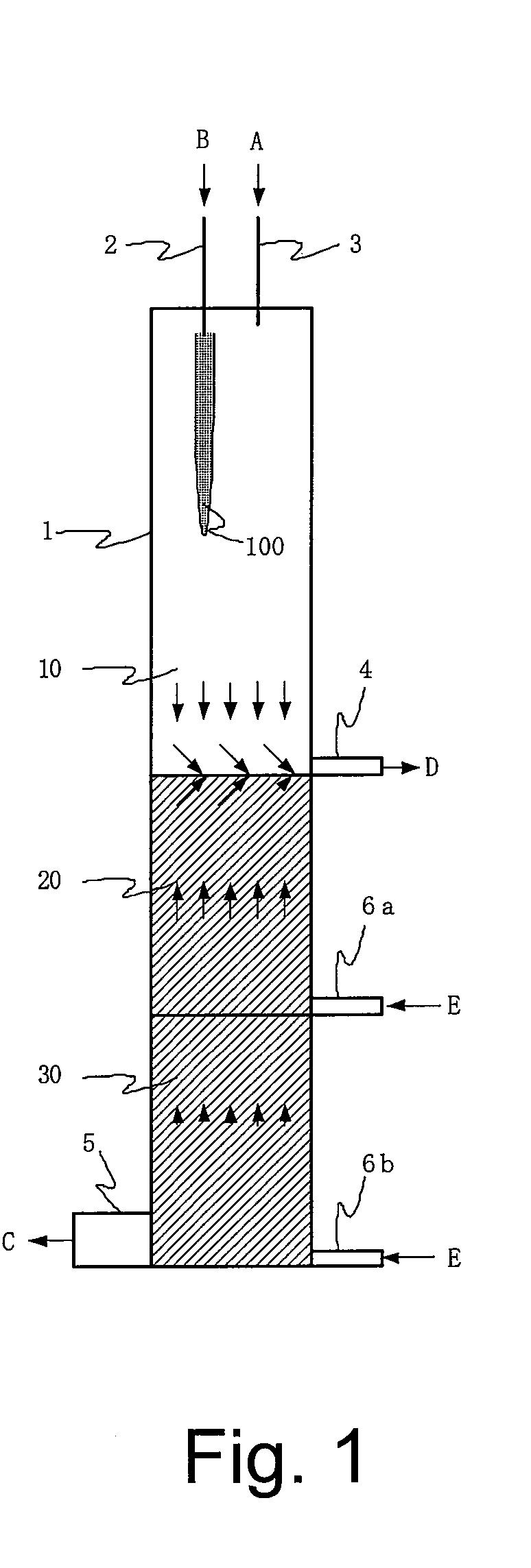
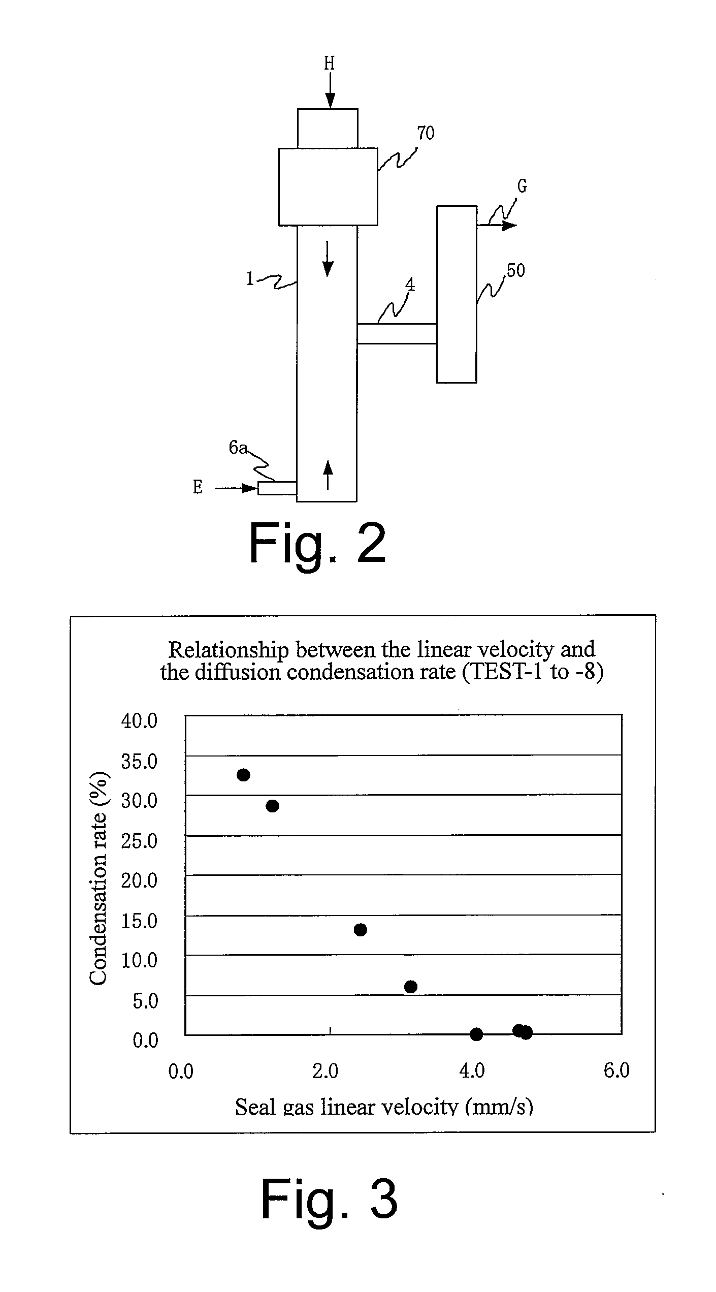
[0086]A test of the method for preventing a by-product gas from diffusion or inflow into a seal gas layer was conducted using an apparatus shown in FIG. 2. The reactor 1 was made of quartz and had a size of about 1000 mm in height and 50 mm in diameter. In the upper part of the reactor 1, a device for heating and generating a zinc chloride gas 70 by which gasified zinc chloride is generated by external heat was incorporated. In the middle part, there was provided an exhaust gas extracting pipe 4 with about 30 mm diameter, and a tank for recovering reducing agent chloride 50 made of glass and having a size of about 600 mm in height and 50 mm in diameter was connected to the tip of the exhaust gas extracting pipe. In the lower part, there was provided a seal gas introducing pipe 6a, and a seal gas was fed from a device for heating and feeding a seal gas. In this test, silicon tetrachloride was used as the seal gas. In the upper part, there was provided a pipe for introducing the balan...

example 2

[0089]A production test of polycrystalline silicon was conducted using the test production apparatus constituted as shown in the schematic diagram exemplified in FIG. 4 and the quality was checked. The reactor was made of quartz and had a structure combining a quartz cylinder of 200 mm in inner diameter and 3350 mm in length as the upper member and a stainless steel cylinder of 200 mm in inner diameter and 1300 mm in length as the lower member. At a height 2000 mm apart from the upper part of the test apparatus, an exhaust gas extracting pipe of 40 mm in inner diameter and 700 mm in length was attached, and there was provided a seal gas introducing opening at a height of 3500 mm. In the central part of the ceiling of the reactor, one silicon chloride feeding pipe made of quartz and having an inner diameter of 20 mm, of which the tip had been processed to be thin-walled was inserted. Further, at a position 60 mm apart from the center toward the circumference, reducing agent gas feedi...


PUM

PropertyMeasurementUnit
Temperatureaaaaaaaaaa
Velocityaaaaaaaaaa
Temperatureaaaaaaaaaa

Abstract

Provided is a production method and a production apparatus using a method for producing a solid product by a reaction of gaseous raw materials with a plurality of components including a step of conducting the reaction using a reactor disposed in a vertical direction; a step of feeding the gaseous raw materials with a plurality of components from the upper part of the reactor; a step of, in the lower part of the reactor, forming a seal gas layer composed of a gas having a high density and fed continuously from the lower part of the reactor; a step of discharging an exhaust gas containing a by-product gas generated by the reaction and unreacted gaseous raw materials from somewhere in the upper part of the formed seal gas layer; and a step of accommodating a solid product in the seal gas layer of the lower part.

Description

CROSS-REFERENCE TO RELATED APPLICATION[0001]This application claims the priority benefit of Japan application serial no. JP2007-061207, filed Mar. 12, 2007. All disclosure of the Japan application is incorporated herein by reference.BACKGROUND OF THE INVENTION[0002]1. Field of the Invention[0003]The present invention relates to a method and an apparatus for producing a solid product with a high purity using a reaction of gaseous raw materials with a plurality of components.[0004]2. Description of Related Art[0005]As a technique for producing a solid product using a reaction of gaseous raw materials with plurality of components, there is known a technique by which a metal with a high purity is produced by a gas phase reaction of a metal chloride gas and a reducing agent gas.[0006]For example, there are disclosed a technique for producing ultrafine nickel powder by a gas phase reduction of a nickel chloride gas with a hydrogen gas (for example, see Patent documents 1 and 2) and a tech...

Claims


Application Information

Patent Timeline
IPC IPC(8): C01B33/023B01J19/00
CPCC01P2006/80Y10T117/10C01B33/027C01G9/04H01L21/205H01L21/223
Inventor HONDA, SHUUICHITANAKA, TORUHAYASHIDA, SATOSHI
Owner JNC CORP
Why Eureka
Try Eureka