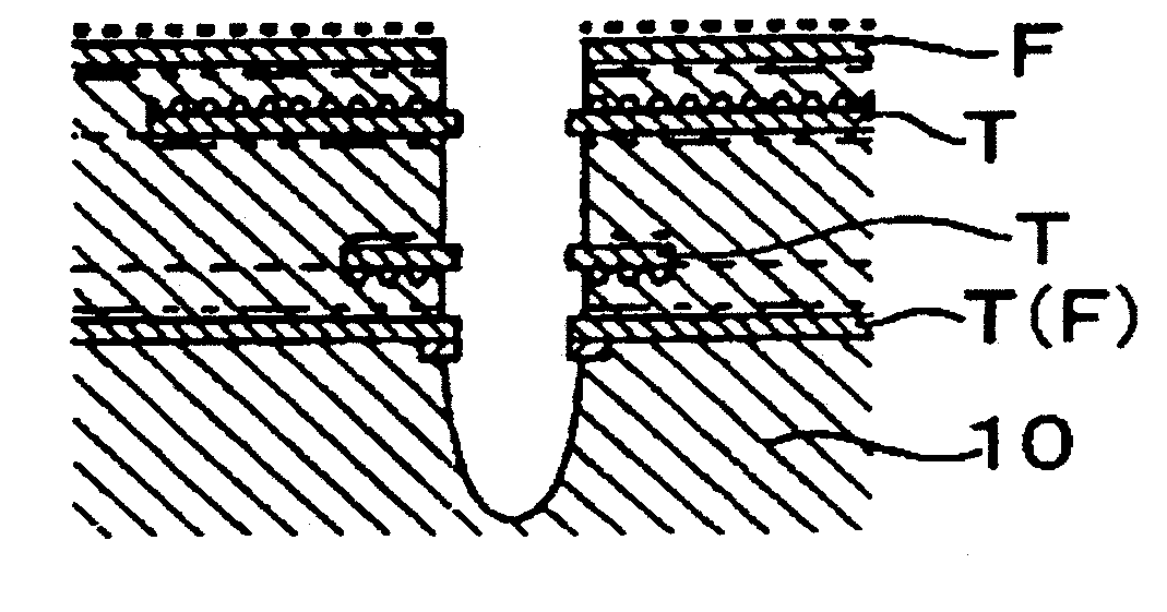
Printed Circuit Board and Method for Processing Printed Circuit Board
a printed circuit board and printed circuit board technology, applied in the direction of dielectric characteristics, light absorption dielectrics, etching metal masks, etc., can solve the problems of increasing the production cost difficult to advance the packaging density of printed circuit boards, and inability to process copper foil sheets, etc., to achieve improved processing efficiency, reduce processing process, and improve the effect of hole quality
- Summary
- Abstract
- Description
- Claims
- Application Information
AI Technical Summary
Benefits of technology
Problems solved by technology
Method used
Image
Examples
embodiment 1
[0031]Processing of a first layer of copper foil disposed in a printed circuit board will be described first. Incidentally, as will be described later, a subject of the invention is a printed circuit board which is provided as a material applied to a process of producing a completed printed circuit board.
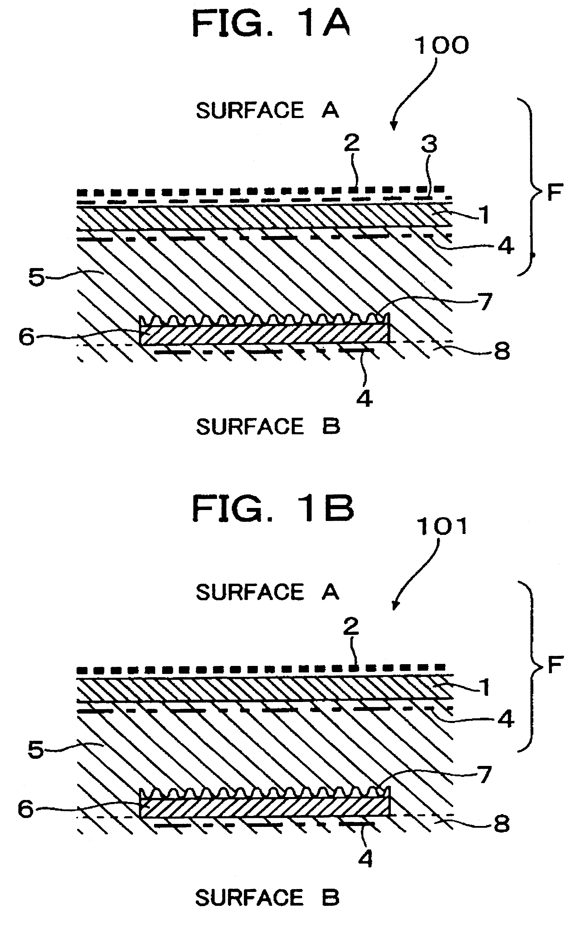
[0032]FIG. 1A is a sectional view typically showing a first printed circuit board 100 according to the invention.
[0033]In the printed circuit board according to the invention, the thickness of a sheet of copper foil 1 which is an electric conductor layer provided as a first layer (hereinafter referred to as “first layer”) is from 5 μm to 18 μm. A Cu2O layer 3 containing Cu2O (cuprous oxide) as a main component as represented by the thick broken line is formed in a portion of a surface (surface A side) abutting on copper. A CuO layer 2 containing CuO (cupric oxide) as a main component as represented by the thin broken line is formed on an upper side (surface A side) of the Cu2O layer...
embodiment 2
[0071]Next, processing of inner layers (the second layer, the electric conductor layer in the second layer, etc.) disposed in the printed circuit board will be described.
[0072]FIGS. 4A to 4D show an example in which the first and second layers ate connected to each other according to the invention. Conductor layers F and S are disposed as the first and second layers respectively. Fiducial marks (alignment marks) 18 are formed at the same time that circuits in the second layer are formed.
[0073]Next, a procedure of processing will be described.
[0074](1) One of the fiducial marks 18 is exposed from the state shown in FIG. 4A. In this case, a beam (Bt) having a top hat type energy distribution is rotated around the center axis of the fiducial mark 18 while the radius of the beam is changed as shown in FIG. 4B. In this manner, the first layer (conductor layer F) is processed by a spot facing treatment. On this occasion, the intensity of the beam can be increased to a certain degree becau...
embodiment 3
[0080]Next, a procedure of processing the blind hole for connecting the first, second and third layers disposed in the printed circuit board will be described.
[0081]FIGS. 5A to 5D show an example in which the first to third layers are connected to one another according to the invention.
[0082](1) One of the fiducial marks 18 is exposed from the state shown in FIG. 5A. In this case, a beam (Bt) having a top hat type energy distribution is rotated around the center axis of the fiducial mark 18 while the radius of the beam is changed. In this manner, the first layer (conductor layer F) is processed by a spot facing treatment. On this occasion, it is necessary to consider that the sheet of copper foil T is prevented from being damaged because the second layer is the sheet of copper foil T (FIG. 5B).
[0083](2) A hole is formed in a desired position of the first layer with reference to the exposed fiducial mark 18.
[0084]In this embodiment, a hole having a diameter of 150 to 200 μm in terms ...
PUM
| Property | Measurement | Unit |
|---|---|---|
| reflectivity | aaaaa | aaaaa |
| thick | aaaaa | aaaaa |
| height | aaaaa | aaaaa |
Abstract
Description
Claims
Application Information
 - R&D
- Intellectual Property
- Life Sciences
- Materials
- Tech Scout
- Unparalleled Data Quality
- Higher Quality Content
- 60% Fewer Hallucinations
Browse by: Latest US Patents, China's latest patents, Technical Efficacy Thesaurus, Application Domain, Technology Topic, Popular Technical Reports.
© 2025 PatSnap. All rights reserved.Legal|Privacy policy|Modern Slavery Act Transparency Statement|Sitemap|About US| Contact US: help@patsnap.com


