Pneumatic Retarder Actuator Valve

a technology of pneumatic retarder and actuator, which is applied in non-electric variable control, process and machine control, instruments, etc., can solve the problems of too little speed, car will not jump the track, and car will damage the coupling mechanism,

Inactive Publication Date: 2008-10-02
AAA SALES ENG
View PDF18 Cites 19 Cited by
  • Summary
  • Abstract
  • Description
  • Claims
  • Application Information

AI Technical Summary

Benefits of technology

[0014]One advantage of the present electro-pneumatic retarder control valve is its modular design, which makes it easy to maintain and repair. The valve has easier service pneumatics. Several “at risk” components including the control valves and their actuating pilot valves are located between two manifolds. These components can be removed as a subassembly, and shipped back to the OEM for trouble shooting. This eliminates the need for trouble shooting at the yard and reduces equipment down time. The modular nature of the control assembly allows a new subassembly to be quickly installed so that the valve is up and running while the faulty subassembly is sent to the OEM for repair. The manifolds also greatly reduce the number of connections and make the assembly of components much faster. The electronics are also easy to replace. Quick disconnects between all input wires and the electronics subassembly facilitate replacement of all electronics in the event of a lightning strike.
[0025]A still further advantage of the present electro-pneumatic retarder control valve is its ergonomic design and reduced noise. The air exhaust mufflers are vertically mounted. Air and sound waves are emitted radially or horizontally. The air waves are directed horizontally within a three sided enclosure. The exhaust air does not impact the ground and propel dust and debris into the air. A three-sided shield also protects maintenance personnel from the exhaust air.

Problems solved by technology

Too little speed, and the car will not make it where they need to go with enough speed to couple with the other cars on the track.
Too much speed, and the car will jump the track or damage the coupling mechanisms.
A problem with conventional pneumatic retarder valves is that they are difficult to maintain.
Diagnosing the source of a problem such as the malfunctioning component is difficult.
The wrong components are frequently replaced in a trial and error effort to fix the valve.
This results in great expense and frustration, and dramatically increases down time.
Another problem with conventional pneumatic retarder valves is the difficulty adjusting the upper and lower limits of the various pressure settings for the valve (LIGHT, MEDIUM, HEAVY and EXTRA-HEAVY).
A further problem with conventional pneumatic retarder valves is that it is difficult to verify whether or not the pressure transducer is providing accurate actual retarder pressure information to the valve.
The electric signal or pressure data sent by the transducer to the circuit board is difficult to measure.
Although an alternate gage can be used to determine the actual pressure from the retarder cylinders that is being received at the retarder valve, there is no easy way to verify that the transducer signal is sending a signal to the circuit board that accurately corresponds to the actual retarder pressure.
Instead of simply replacing a failing or faulty pressure transducer, field personnel attempt to correct the pressure anomalies by adjusting other components such as the variable resisters that set the pressure limits, which fails to correct the underlying problem, can lead to other operational problems in the retarder valve and can lead to accident and injury.
A still further problem with conventional pneumatic retarder valves is their electrical systems.
The systems are polarity sensitive and can be damaged by inadvertently switching the positive and negative leads.
Power surges such as by lightning strikes can also easily damage the electrical system.
A still further problem with conventional pneumatic retarder valves is that the electronics are difficult to replace.
A lightning strike can shut down the control valve for a long time.
A still further problem with conventional pneumatic retarder valves is that they include valves and other components that require frequent lubrication and other maintenance due to the harsh chemicals found in marshalling yards.
A still further problem with conventional pneumatic retarder valves is that they include a large amount of piping and fittings.
These components frequently leak the pressurized air they are meant to contain.
This leaking wastes air, causes the yard compressors to run more frequently, and reduces the capacity of the pressurized air system for the yard.

Method used


Image

  • Pneumatic Retarder Actuator Valve
  • Pneumatic Retarder Actuator Valve
  • Pneumatic Retarder Actuator Valve

Examples


Embodiment Construction

[0048]While this invention is susceptible of embodiment in many different forms, the drawings show and the specification describes in detail a preferred embodiment of the invention. It should be understood that the drawings and specification are to be considered an exemplification of the principles of the invention. They are not intended to limit the broad aspects of the invention to the embodiment illustrated.

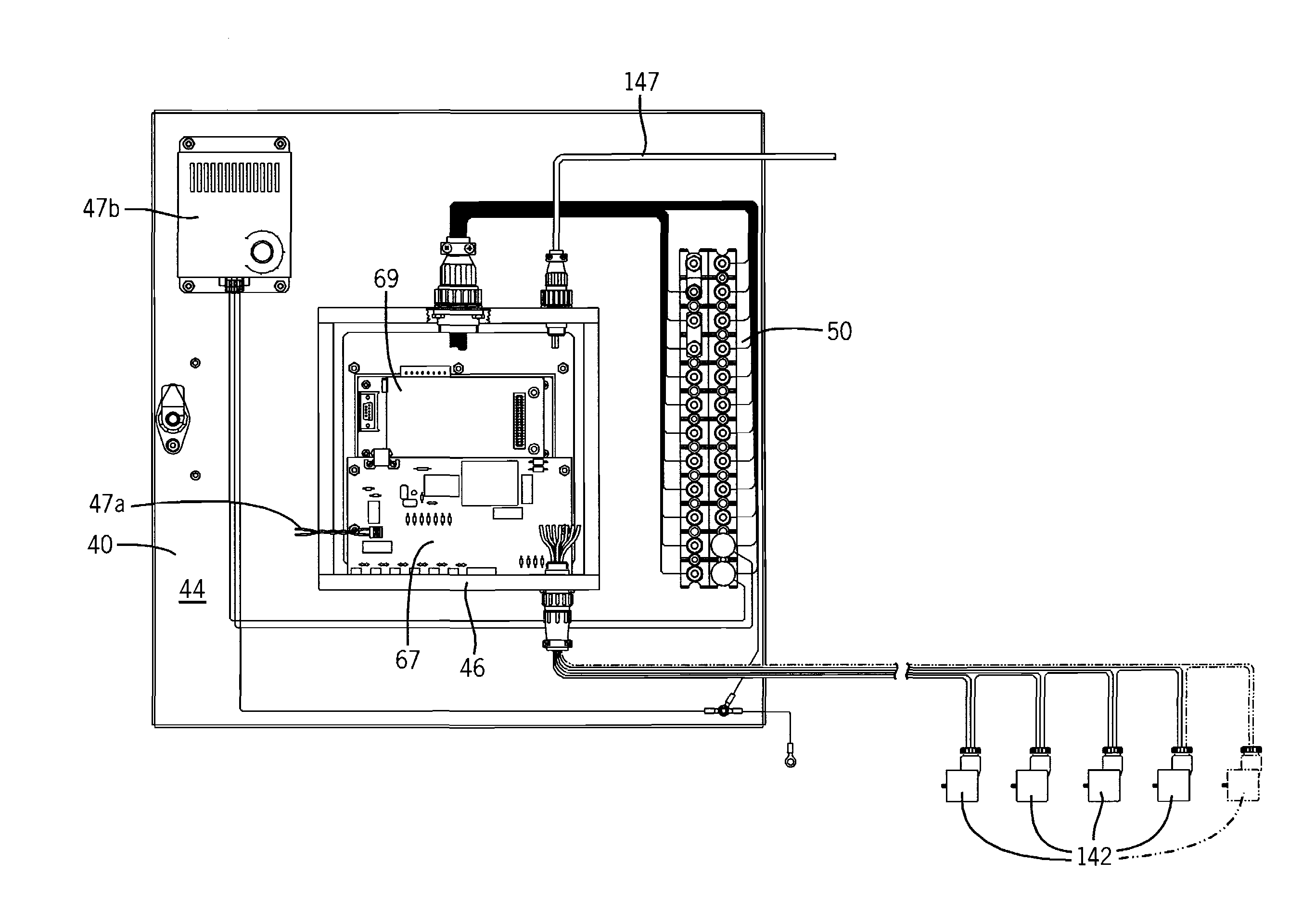
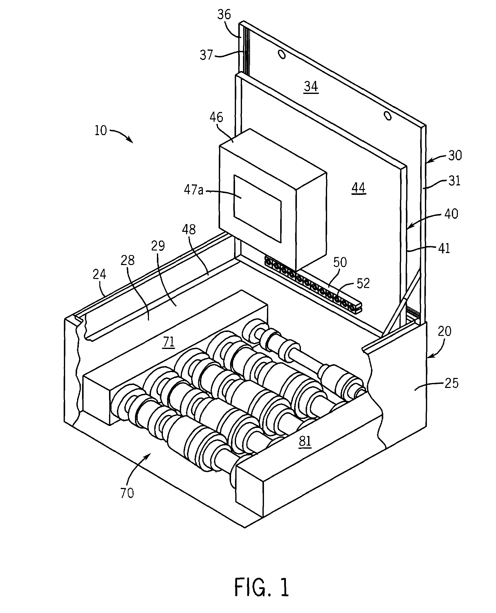
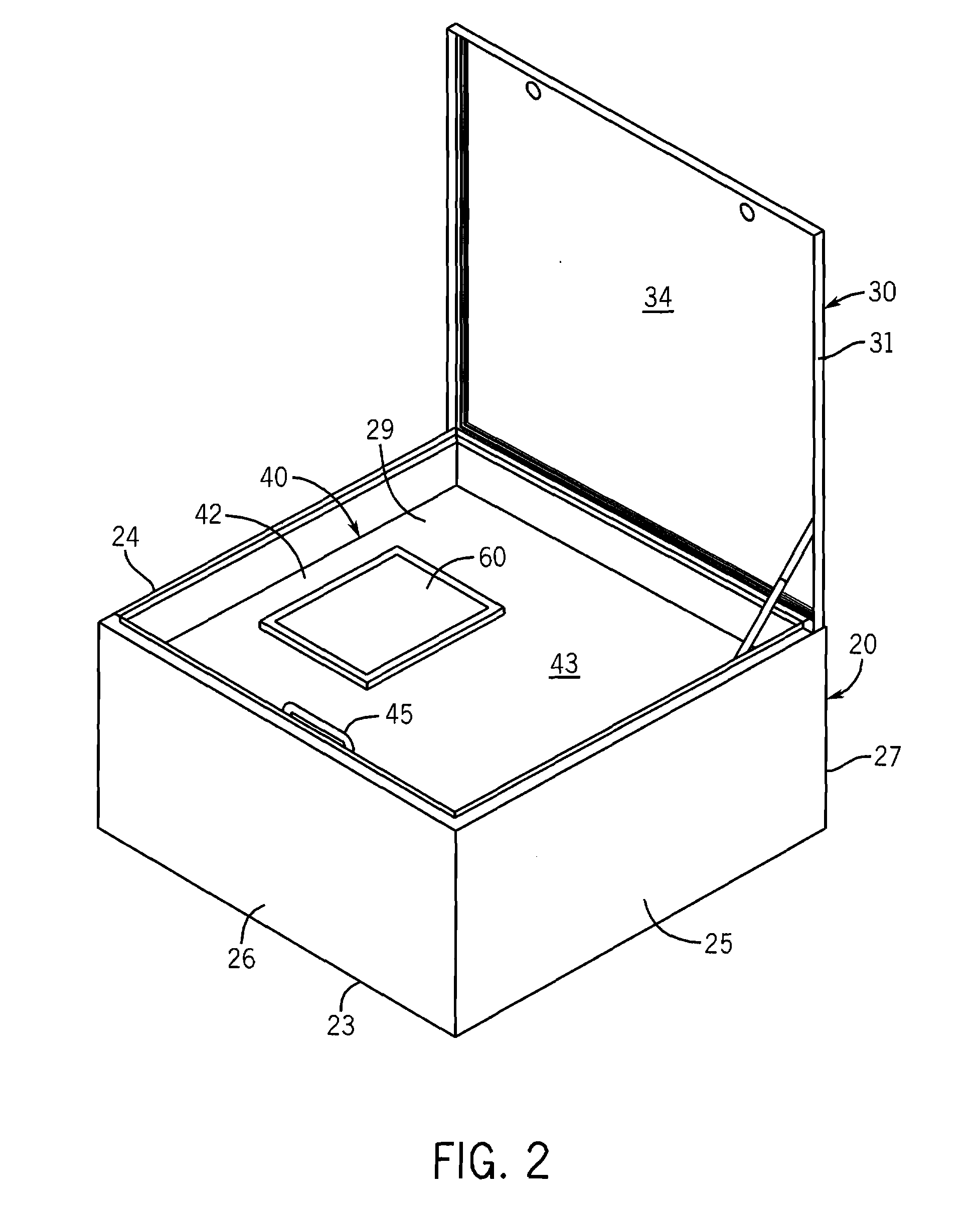
[0049]The present invention relates to an electro-pneumatic retarder control (EPRC) or control valve assembly generally indicated by reference number 10 and shown in FIGS. 1 and 2. The control valve assembly 10 is typically installed within a few feet of a marshalling yard retarder (not shown), which moves its brakes into braking engagement against the wheels of the cars. The valve assembly 10 is divided into four areas or quadrants 11-14. Pressurized air is received by the valve assembly 10 via its intake quadrant 11, and controllably delivers the pressurized air to its suppl...


PUM


Abstract

The present invention pertains to an electro-pneumatic retarder control (EPRC) valve for a pneumatic retarder that controls the speed of railroad cars in a marshaling yard. The EPRC valve has a housing that generally encloses and protects its various components. The housing has a lid that can be opened to gain access to a control panel mounted on an interior door. The control panel includes a display, keyboard and programmable logic controller or PLC module that can be adjusted to set the desired pressure levels of the retarder. The EPRC valve has a modular pressure control assembly that includes an intake and exhaust manifold, a retarder supply and return manifold and several interchangeable control lines formed by like-shaped control valves and components. A pilot air control assembly enables the PLC module to selectively open and close the control valves and lines to deliver or release pressurized air to the retarder.

Description

CROSS-REFERENCE TO RELATED APPLICATION[0001]The present application is a divisional of co-pending U.S. patent application Ser. No. 10 / 477,052, filed Jun. 1, 2004, which application asserts priority on U.S. Provisional Application Ser. No. 60 / 485,541 filed Jul. 8, 2003.TECHNICAL FIELD OF THE INVENTION[0002]The present invention relates to an electro-pneumatic retarder control (EPRC) with a programmable logic controller (PLC) module for controlling the flow of pressurized air supplied to and discharged from a pneumatic retarder in a railroad marshaling yard.BACKGROUND OF THE INVENTION[0003]Railroad retarders control the speed of railroad cars in a marshalling yard. Cars sent over the hump of the yard gain speed as they roll down the hump and are routed via a number of switches to an appropriate track for coupling to other cars on that track. The speed of the cars vary depending on the weight of the car, the speed it is sent over the hump, the number of switches and length of track it ...

Claims


Application Information

Patent Timeline
Patent Type & Authority Applications(United States)
IPC IPC(8): F16K31/12G05D7/06B61K7/08
CPCB61K7/08Y10T137/87217Y10T137/87507Y10T137/5283
Inventor HEYDEN, THOMAS J.ZIESE, LOWELL B.BRAATZ, JAMES D.
Owner AAA SALES ENG
Why Eureka
Try Eureka