Device that enables plasma ignition and complete faraday shielding of capacitive coupling for an inductively-coupled plasma

a capacitive coupling and capacitive coupling technology, applied in plasma techniques, electrical equipment, electric discharge tubes, etc., can solve the problems of increasing the power consumption of the gate, unsatisfactory effects on the performance and durability of the gate, and increasing the leakage current of the ga

Inactive Publication Date: 2008-10-02
APPLIED MATERIALS INC
View PDF23 Cites 18 Cited by
  • Summary
  • Abstract
  • Description
  • Claims
  • Application Information

AI Technical Summary

Benefits of technology

[0014]One embodiment of the present invention is a method for processing a substrate. The method generally includes locating the substrate within a substantially enclosed volume of a plasma reactor; performing an action to initiate ignition of a gas mixture within the enclosed volume into a plasma by supplying power to one or more radio frequency (RF) coils disposed adjacent to the enclosed volume; in response to detecting an event indicative of plasma ignition, connecting an electrode interposed between the RF coils and the enclosed volume to a ground source to prevent capacitive coupling of the power to the plasma; and further processing the substrate using inductively-coupled plasma.
[0015]Another embodiment of the present invention is a method for processing a substrate. The method generally includes locating the substrate within a substantially enclosed volume of a plasma reactor; performing an action to initiate ignition of a gas mixture within the enclosed volume into a plasma by supplying power to one or more RF coils disposed adjacent to the enclosed volume; in response to detecting an event indicative of plasma ignition, connecting an electrode interposed between the RF coils and the enclosed volume to a ground source to prevent capacitive coupling of the power to the plasma; and further processing the substrate while the electrode is cycled between being connected and disconnected from the ground source.

Problems solved by technology

Attempts have been made to reduce the thickness of SiO2 gate dielectrics below 20 Å. However, it has been found that the use of SiO2 gate dielectrics below 20 Å often results in undesirable effects on gate performance and durability.
Also, there is typically an increase in gate leakage current, i.e., tunneling current, with thin dielectrics that increases the amount of power consumed by the gate.
Thin SiO2 gate dielectrics may be susceptible to NMOS (n-channel metal oxide semiconductor) hot carrier degradation, in which high energy carriers traveling across the dielectric can damage or destroy the channel.
Thin SiO2 gate dielectrics may also be susceptible to PMOS (p-channel metal oxide semiconductor) negative bias temperature instability (NBTI), wherein the threshold voltage or drive current drifts with operation of the gate.
This may result in a gate leakage reduction, due to tunneling during the operation of a FET, at the same EOT as the un-nitrided oxide dielectric.
Since such a strong electric field causes ions or electrons to be accelerated with high kinetic energy towards the substrate surface, capacitive coupling may cause excessive bombardment of the surface of a substrate, such as the silicon dioxide layer, by nitrogen ions, for example, which can cause damage to the substrate surface.
However, devices for maintaining inductively-coupled plasma typically cannot ignite the plasma because inductive coupling cannot generate high energy electrons to start the avalanche process described above.
In such systems, either a secondary excitation source using capacitively-coupled RF is employed or the inductively-coupled RF source has a small capacitively-coupled element present to ignite the plasma, which may still lead to some damage to the substrate surface.

Method used


Image

  • Device that enables plasma ignition and complete faraday shielding of capacitive coupling for an inductively-coupled plasma
  • Device that enables plasma ignition and complete faraday shielding of capacitive coupling for an inductively-coupled plasma
  • Device that enables plasma ignition and complete faraday shielding of capacitive coupling for an inductively-coupled plasma

Examples


Embodiment Construction

[0025]Embodiments of the present invention provide a means to ignite a gas mixture into plasma using capacitive coupling techniques, shield the plasma and other contents of the plasma reactor from the capacitively-coupled electric field, and maintain the plasma using inductive coupling. Such techniques are employed in an effort to prevent damage to the surface of a substrate from excessive ion bombardment caused by the highly energized ions and electrons accelerated towards and perpendicular to the substrate surface by the electric field of capacitively-coupled plasma.

An Exemplary Plasma Reactor

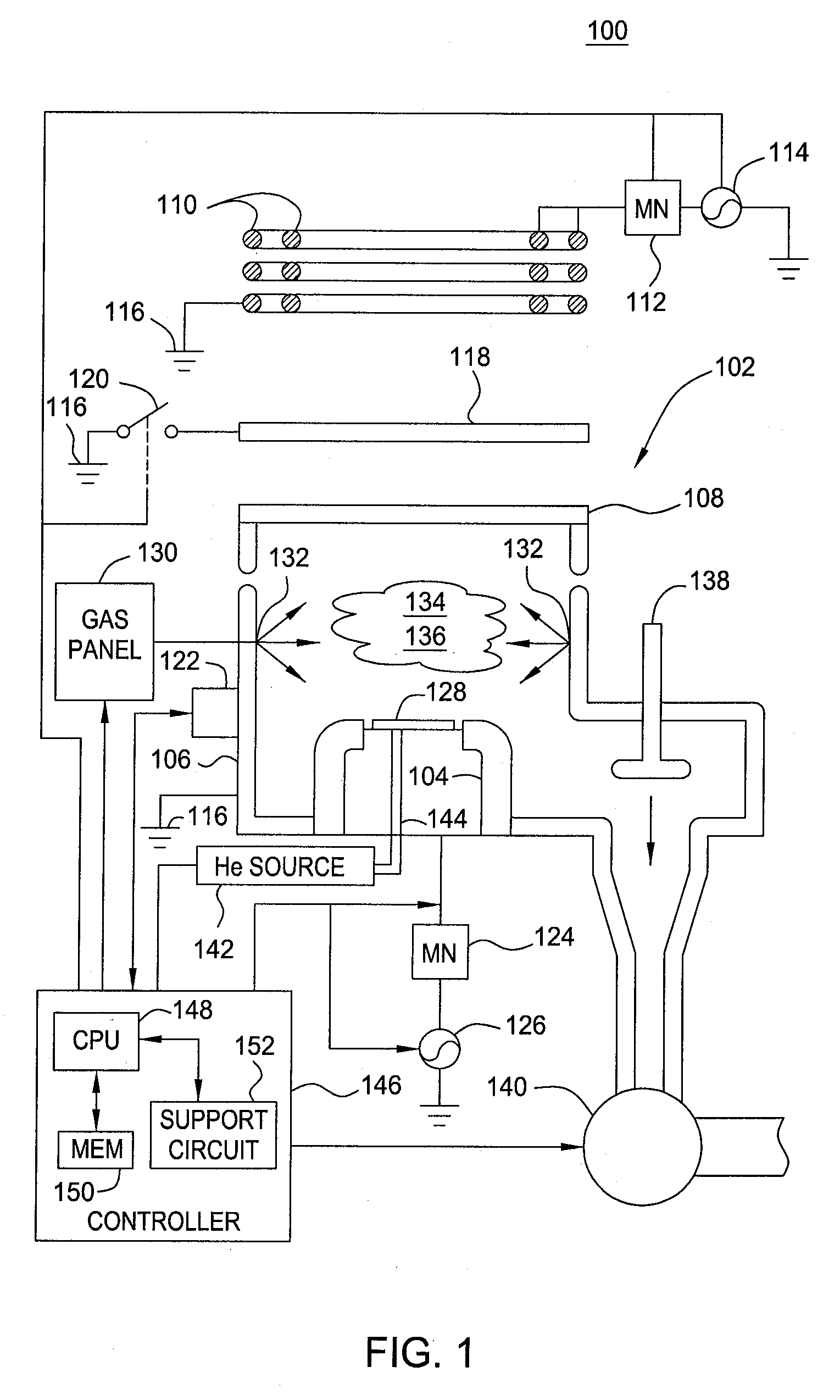
[0026]FIG. 1 depicts a schematic, cross-sectional diagram of a plasma reactor 100 that may be used to ignite plasma according to embodiments of the present invention. The plasma reactor 100 may be a slightly modified version of the Decoupled Plasma Nitridation (DPN) or DPN Plus chambers made by Applied Materials located in Santa Clara, Calif. Primarily an inductive plasma source reactor, plas...


PUM


Abstract

A method and apparatus for igniting a gas mixture into plasma using capacitive coupling techniques, shielding the plasma and other contents of the plasma reactor from the capacitively-coupled electric field, and maintaining the plasma using inductive coupling are provided. For some embodiments, the amount of capacitive coupling may be controlled after ignition of the plasma. Such techniques are employed in an effort to prevent damage to the surface of a substrate from excessive ion bombardment caused by the highly energized ions and electrons accelerated towards and perpendicular to the substrate surface by the electric field of capacitively-coupled plasma.

Description

BACKGROUND OF THE INVENTION[0001]1. Field of the Invention[0002]Embodiments of the present invention generally relate to plasma nitridation and, more particularly, to methods and apparatus for igniting and maintaining a plasma without causing ion bombardment damage to a device.[0003]2. Description of the Related Art[0004]Integrated circuits (ICs) are composed of many, e.g., millions, of devices such as transistors, capacitors, and resistors. Transistors, such as field effect transistors (FETs), typically include a source, a drain, and a gate stack. The gate stack generally includes a substrate, such as a silicon substrate, a gate dielectric, and a gate electrode, such as polycrystalline silicon, on the gate dielectric. The gate dielectric layer is formed of dielectric materials such as silicon dioxide (SiO2), or a high-k dielectric material having a dielectric constant greater than 4.0, such as SiON, SiN, hafnium oxide (HfO2), hafnium silicate (HfSiO2), hafnium silicon oxynitride (H...

Claims


Application Information

Patent Timeline
Patent Type & Authority Applications(United States)
IPC IPC(8): H05H1/24
CPCH01J37/321H01J37/32623H01J37/32697
Inventor CHUA, THAI CHENGCRUSE, JAMES P.CZARNIK, CORY
Owner APPLIED MATERIALS INC
Why Eureka
Try Eureka