Semiconductor Device, Television Set, and Method for Manufacturing The Same

a technology of semiconductor devices and television sets, which is applied in the direction of semiconductor devices, electrical equipment, instruments, etc., can solve the problems of reducing the throughput or yield of the semiconductor device formed, clogging the opening, and difficult to continuously and stably discharge a certain amount of discharge solution, so as to reduce the cost, simplify the process, and improve the effect of accuracy

Inactive Publication Date: 2008-10-09
SEMICON ENERGY LAB CO LTD
View PDF15 Cites 28 Cited by
  • Summary
  • Abstract
  • Description
  • Claims
  • Application Information

AI Technical Summary

Benefits of technology

[0006]The present invention is made in view of such problems and, it is an object of the invention to provide a method for manufacturing a semiconductor element having a minute structure, and further, a semiconductor device and a television set having a high throughput or a high yield at low cost and a manufacturing method thereof.
[0031]When a droplet discharge method is employed in forming a film pattern, a droplet can be discharged to an arbitrary position by changing a relative position of a nozzle that is a discharge opening of a droplet including a film material thereofs and a substrate. In addition, a thickness and a width of a pattern to be formed can be adjusted depending on a nozzle diameter, the discharge amount of droplets, and a relative relationship between movement speed of a nozzle and that of a substrate to be provided with a discharged droplet. Accordingly, a film pattern can be formed in a desired portion with high accuracy by discharging even over a large area semiconductor element substrate having a side of 1 m to 2 m or more. Since light exposure and development process using a photomask can be omitted, simplification of a process and reduction in cost can be achieved.
[0032]Further, a semiconductor device such as a highly integrated circuit or a display device having a high aperture ratio, or a television set can be manufactured at low cost with high throughput and yield by using a semiconductor element with a minute structure.

Problems solved by technology

When a diameter of a discharge opening is made small for this reason, a composition of a discharge solution may be attached to an a discharge opening, dried, and solidified, and a clogged opening or the like may be caused.
Thus, it is difficult to continuously and stably discharge a certain amount of discharge solution.
Consequently, there is a problem of causing decrease in a throughput or a yield of a semiconductor device formed with the semiconductor element.

Method used


Image

  • Semiconductor Device, Television Set, and Method for Manufacturing The Same
  • Semiconductor Device, Television Set, and Method for Manufacturing The Same
  • Semiconductor Device, Television Set, and Method for Manufacturing The Same

Examples


embodiment mode 1

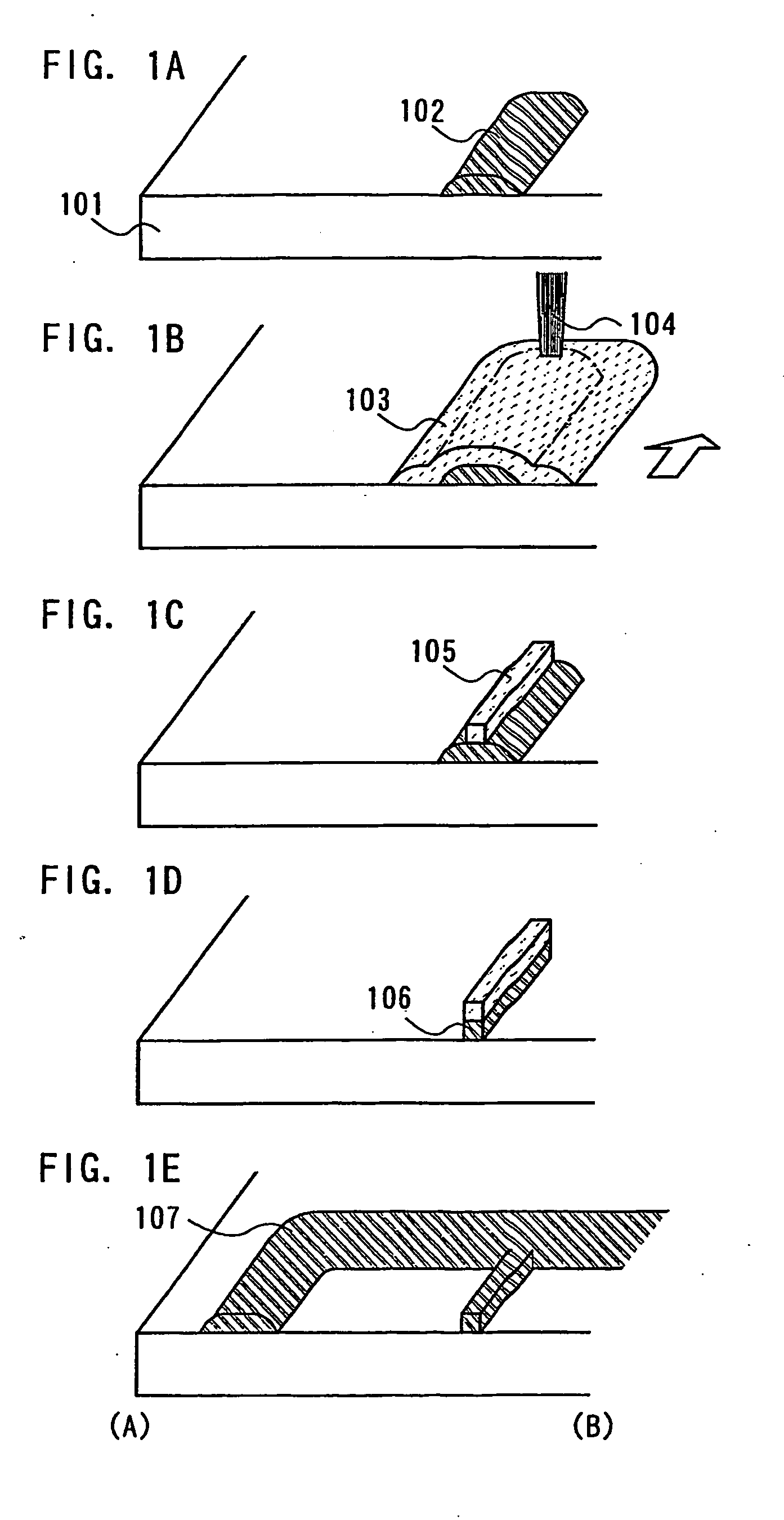
[0069]A step of forming a narrow wiring using a mask pattern formed by being irradiated with a laser beam (hereinafter, also referred to as laser light) is described in this embodiment mode with reference to FIGS. 1A to 1E and FIG. 2.

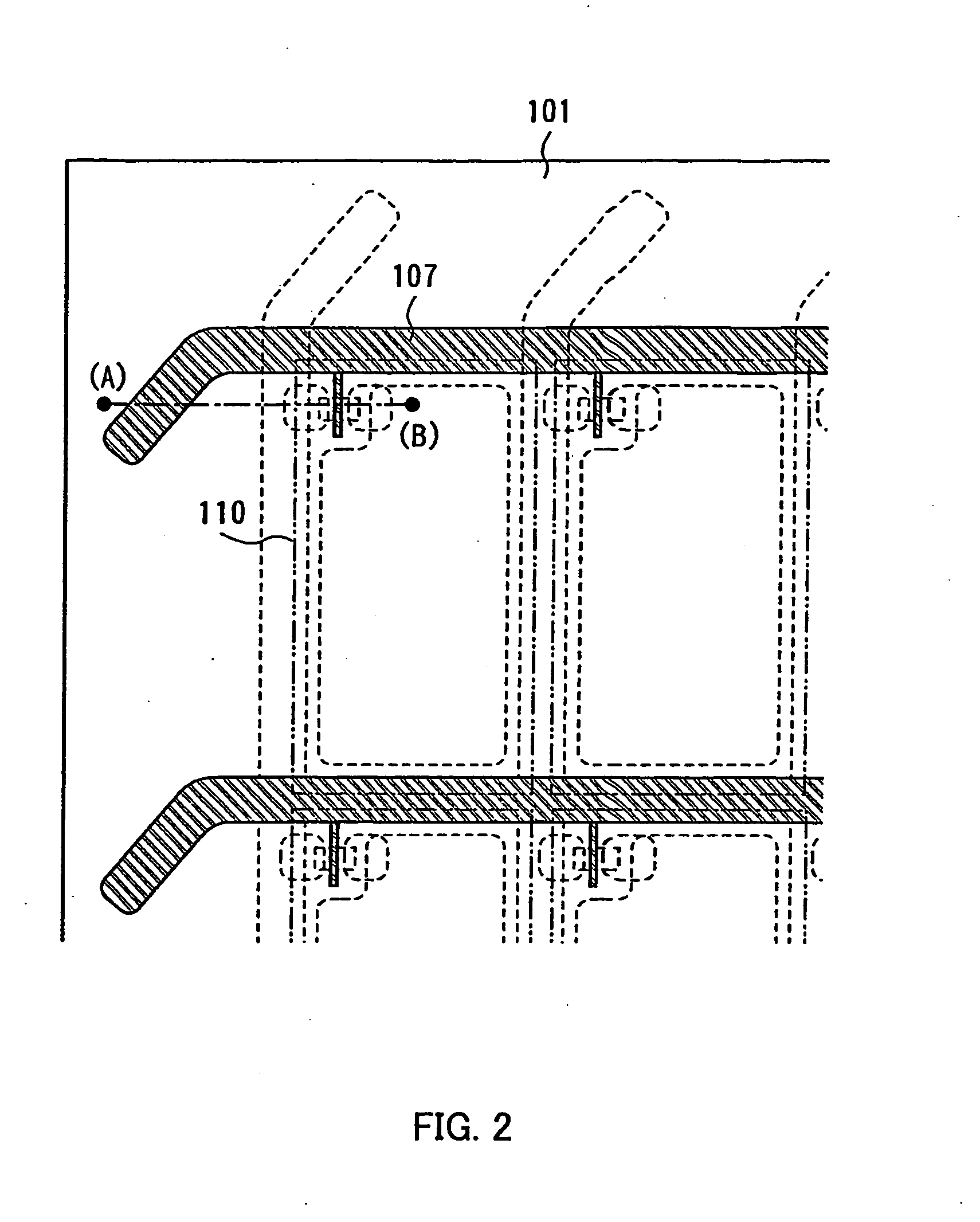
[0070]FIG. 2 is a plan view of a substrate 101 in which a pixel 110 is arranged in a matrix. A third conductive layer 107 which functions as a gate wiring of a semiconductor element to be formed later is shown in solid line over the substrate 101. In addition, a source wiring, a semiconductor region, a source electrode, a drain electrode, a pixel electrode, and the like of a semiconductor element to be formed later are shown in dashed line.

[0071]FIGS. 1A to 1E are front perspective views of the substrate in FIG. 2 taken along a line A-B. A manufacturing process of the invention is described with reference to FIGS. 1A to 1E.

[0072]A first conductive layer 102 is formed over the substrate 101 by a droplet discharge method as shown in FIG. 1A.

[0073]As the s...

embodiment mode 2

[0094]A method for manufacturing a semiconductor element is described hereinafter. The following embodiment mode is described using a TFT as a semiconductor element; however, the invention is not limited thereto. An organic semiconductor transistor, a diode, a MIM element, a memory element, a diode, a photoelectric conversion element, a capacitor element, a resistor element, or the like can be used.

[0095]In this embodiment mode, a step of manufacturing a channel etch type TFT that is one of an inversely staggered type (bottom gate type) TFT as a semiconductor element is described with reference to FIGS. 3A to 3F.

[0096]As shown in FIG. 3A, a first conductive layer 302 is formed over a substrate 101. A droplet discharge method is employed as a formation method of the first conductive layer 302. In addition, the same conductive material as the first conductive layer 102 described in Embodiment Mode 1 can be appropriately used as a material of the first conductive layer.

[0097]Before the...

embodiment mode 3

[0116]A step of manufacturing a channel protective type (channel stopper type) TFT is described in this embodiment mode with reference to FIGS. 4A to 4E.

[0117]As in Embodiment Mode 2, after performing steps shown in FIGS. 4A and 4B, a gate electrode 321, a first insulating film 322, and a first semiconductor film 323 are formed over a substrate 101 as shown in FIG. 4C.

[0118]Subsequently, a protective film 401 is formed in a region over the first semiconductor film 323, which overlaps the gate electrode 321. The protective film is preferably formed by using a heat resistant high molecular weight material. It is preferable to use a high molecular weight material which has an aromatic ring or a heterocyclic ring as a main chain, has few aliphatic portions, and includes high polar heteroatom groups. As a typical example of such a high molecular weight material, polyimide, polybenzimidazole, or the like can be given. In the case of using polyimide, a composition containing polyimide is d...


PUM

PropertyMeasurementUnit
widthaaaaaaaaaa
widthsaaaaaaaaaa
viscosityaaaaaaaaaa

Abstract

An object of the invention is to provide a method for manufacturing a substrate having a film pattern such as an insulating film, a semiconductor film, or a conductive film with an easy process, and further, a semiconductor device and a television set having a high throughput or a high yield at low cost and a manufacturing method thereof. One feature of the invention is that a first film pattern is formed by a droplet discharge method, a photosensitive material is discharged or applied to the first film pattern, a mask pattern is formed by irradiating a region where the first film pattern and the photosensitive material are overlapped with a laser beam and by developing, and a second film pattern having a desired shape is formed by etching the first film pattern using the mask pattern as a mask.

Description

TECHNICAL FIELD[0001]The present invention relates to a semiconductor device and a television set having a semiconductor element formed by a droplet discharge method typified by an ink-jet method and to a method for manufacturing the semiconductor device and the television set.BACKGROUND ART[0002]In manufacturing of a semiconductor device, consideration is given to using a droplet discharge method to form a pattern of a thin film or a wiring used for a semiconductor element with a view to reduction in cost of equipment and simplification of a process.[0003]On this occasion, in forming a film pattern in a semiconductor element, a film pattern is formed by performing a photolithography step of applying a resist to an entire surface of a substrate, prebaking, and then irradiating with ultraviolet rays or the like with a mask pattern therebetween and developing to form a resist pattern, and by etching and removing a film existing in a portion to be a film pattern (a film formed of a sem...

Claims


Application Information

Patent Timeline
Patent Type & Authority Applications(United States)
IPC IPC(8): H01L33/00H01L21/00G02F1/1362H01L21/336H01L21/77H01L21/84H01L29/417
CPCG02F2001/136295H01L29/41733H01L27/1292H01L29/66765H01L29/66757G02F1/136295H01L21/6715H01L27/1214
Inventor YAMAZAKI, SHUNPEISHOJI, HIRONOBUARAI, YASUYUKI
Owner SEMICON ENERGY LAB CO LTD
Why Eureka
Try Eureka