
Method and Apparatus for In-Line Process Control of the Cigs Process

a technology of in-line process control and cigs, which is applied in the direction of sustainable manufacturing/processing, final product manufacturing, coatings, etc., can solve the problem that the patent does not disclose any means, and achieve the effect of improving the precision, high substrate output rate, and accurately controlling the thickness and composition of the cigs material

Active Publication Date: 2008-10-16
SOLIBRO RES AB
View PDF12 Cites 30 Cited by
  • Summary
  • Abstract
  • Description
  • Claims
  • Application Information

AI Technical Summary

Benefits of technology

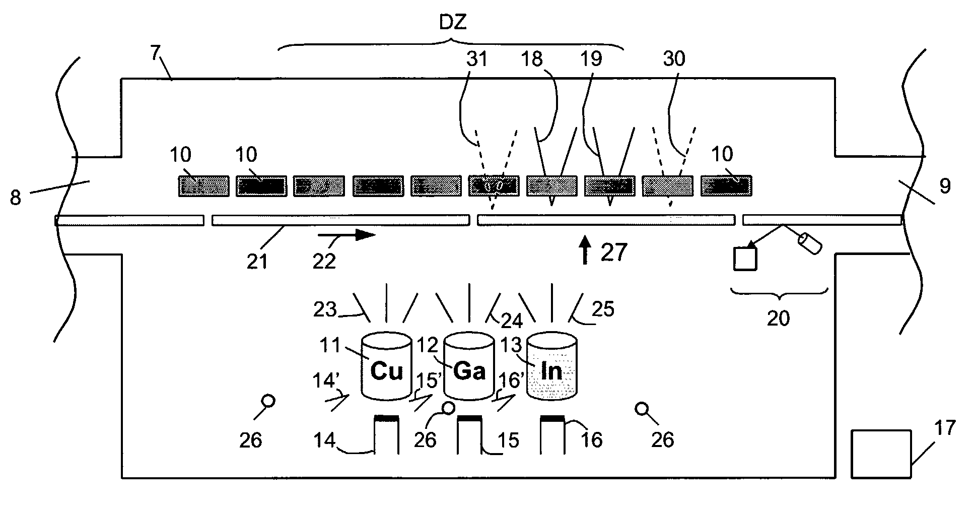
[0013]One object of the present invention is to provide a control method for accurate control of the co-deposited CIGS layer in an in-line system for fabrication of CIGS solar cells, wherein substrates provided with a molybdenum back contact layer continuously move through a CIGS process chamber.
[0014]Another object of the invention is to provide a uniform deposition of the CIGS layer over the width of the substrates as seen in the transport direction of the substrates through the process chamber. This is achieved by using at least two rows of evaporation sources, as seen in the transport direction of the substrates through the process chamber, the evaporation sources in one row being controlled more or less independently of the sources of the other rows in order to provide a uniform thickness and a uniform composition of the CIGS layer.
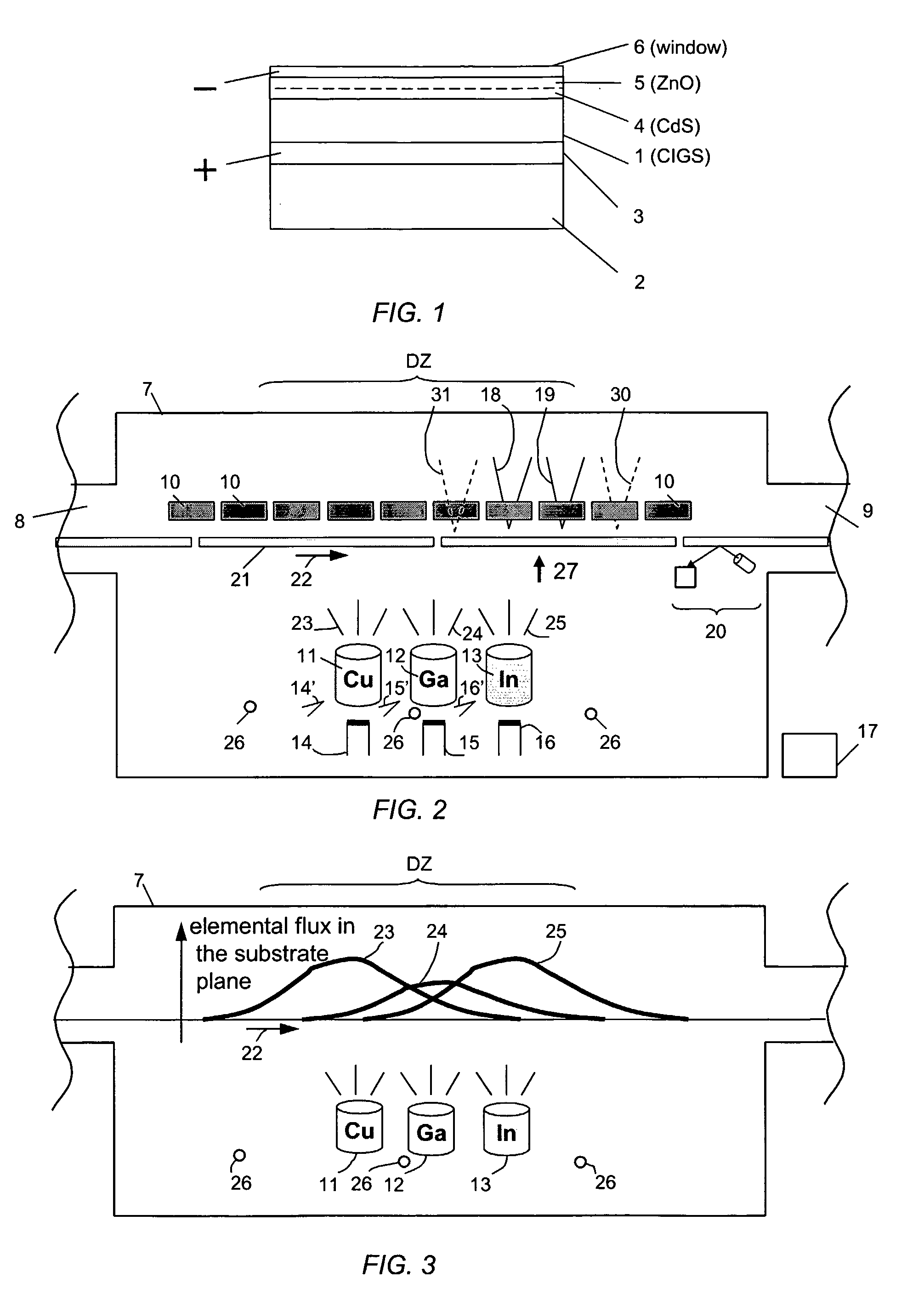
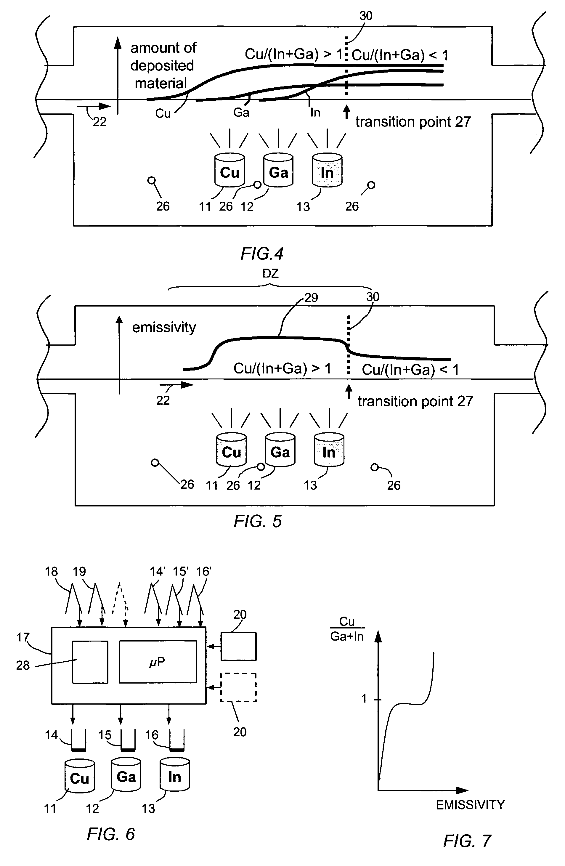
[0016]One control method in accordance with the invention is based on the fact that several physical and chemical properties of the CIGS material changes abruptly when the CIGS layer is transformed from a Cu-excessive to Cu-deficient composition. In particular the travelling CIGS layer transforms from a two-phase material comprising Cu(In,Ga)Se2 and CuxSe into a single phase material comprising Cu(InGa)Se2. The control method is independent of the method used for the manufacture of the CIGS layer. In accordance with the invention the position in the CIGS process chamber at which the transformation takes place, this position being referred to as a reference transition point, is detected. Further, by detecting a shift of the position at which the transformation occurs, this position being referred to as the actual transition point, from the reference transition position and take a corrective action to bring the actual transition point back to the reference transition point it is possible to accurately control the composition of the CIGS layer.
[0018]Two sensors forming a sensor pair may be used in order to detect the transition point. The sensors of a pair are arranged at each side of the transition point. There may be two or more sensor pairs arranged over the width of the process chamber in order to detect a respective transition point. A set of evaporation sources is associated with each sensor pair. Each sensor pair and its associated set of evaporation sources are connected to a respective controller. A controller adjusts any of its associated evaporation sources in order to keep its respective transition point generally still. Control takes place by adjusting the power to the relevant evaporation source heater. The use of several sensor pairs arranged over the width of the process chamber enhances the precision with which the CIGS layer is deposited as seen in a direction over the width of the process chamber.
[0019]By providing an x-ray fluorescence composition measuring apparatus, below referred to as an XRF device, downstream the reference transition point it is possible to accurately control the thickness and composition of the CIGS material, thus proving a high output rate of substrates that have accurately controlled composition and thickness.
[0020]The method provides a fast feed-back loop in order to achieve good control dynamics.

Problems solved by technology

The patent does not disclose any means for detecting a transformation of a copper rich CIGS composition into a copper deficient CIGS composition.

Method used


Image

  • Method and Apparatus for In-Line Process Control of the Cigs Process
  • Method and Apparatus for In-Line Process Control of the Cigs Process
  • Method and Apparatus for In-Line Process Control of the Cigs Process

Examples


Embodiment Construction

[0037]Refer to FIG. 1. The commonly used way of fabricating CIGS solar cells is includes the growth of a CIGS layer 1 on a substrate material 2, such as sheet glass or metal foil, which has been coated with a layer of Mo 3. The Mo layer serves as back contact of the solar cell. The CIGS growth is followed by the formation of a pn-junction by deposition of a buffer layer 4, typically 50 nm of CdS, an optional high resistivity thin layer of ZnO 5 and a front contact of a transparent conductive oxide 6. One critical factor for obtaining solar cells with high light to electricity conversion efficiency is the quality of the CIGS material.

[0038]Although the invention will be described in connection with a horizontal deposition system, it should be understood the present invention can be used with a vertical deposition system. In FIG. 2 the deposition system comprises a process chamber 7 for the inventive fabrication of a CIGS layer. The process chamber is shown to comprise an inlet 8, an ...


PUM

PropertyMeasurementUnit
Temperatureaaaaaaaaaa
Thicknessaaaaaaaaaa
Compositionaaaaaaaaaa

Abstract

An in-line production apparatus and a method for composition control of copper indium gallium diselenide (CIGS) solar cells fabricated by a co-evaporation deposition process. The deposition conditions are so that a deposited Cu-excessive overall composition is transformed into to a Cu-deficient overall composition, the final CIGS film. Substrates with a molybdenum layer move through the process chamber with constant speed. The transition from copper rich to copper deficient composition on a substrate is detected by using sensors which detect a physical parameter related to the transition. A preferred embodiment sensors are provided that detect the composition of elements in the deposited layer. A controller connected to the sensors adjusts the fluxes from the evaporant sources in order provide a CIGS layer with uniform composition and thickness over the width of the substrate.

Description

TECHNICAL FIELD OF THE INVENTION[0001]The invention relates to a method and apparatus for fabrication of copper indium gallium diselenide (CIGS) solar cells by a co-evaporation deposition process in a process chamber. The invention also relates to a method and device for control of the thickness and composition of the deposited CIGS layer.TECHNICAL BACKGROUND[0002]Solar cells provide a means to produce electric power with minimal environmental impact because it is a renewable technology. In order to become a commercial success the solar cells need to be efficient, to have low cost, to be durable, and not add other environmental problems.[0003]Today's dominant solar cell technology is based on crystalline silicon. It fulfils many of the requirements mentioned above but can not be produced at such low cost that electricity generation in large scale is cost effective. It also requires relatively large amount of energy in the production, which is an environmental disadvantage.[0004]Sola...

Claims


Application Information

Patent Timeline
IPC IPC(8): B05D5/12B05C11/00H01LH01L31/032
CPCC23C14/0623C23C14/548H01L31/18H01L31/0322Y02E10/541C23C14/56H01L21/02491H01L21/02568H01L21/02631Y02P70/50H01L31/0445
Inventor STOLT, LARSKESSLER, JOHN
Owner SOLIBRO RES AB
Learn More