
Hydrocarbon recovery and light product purity when processing gases with physical solvents

Inactive Publication Date: 2008-10-23
ADVANCED EXTRACTION TECH
View PDF25 Cites 14 Cited by
  • Summary
  • Abstract
  • Description
  • Claims
  • Application Information

AI Technical Summary

Benefits of technology

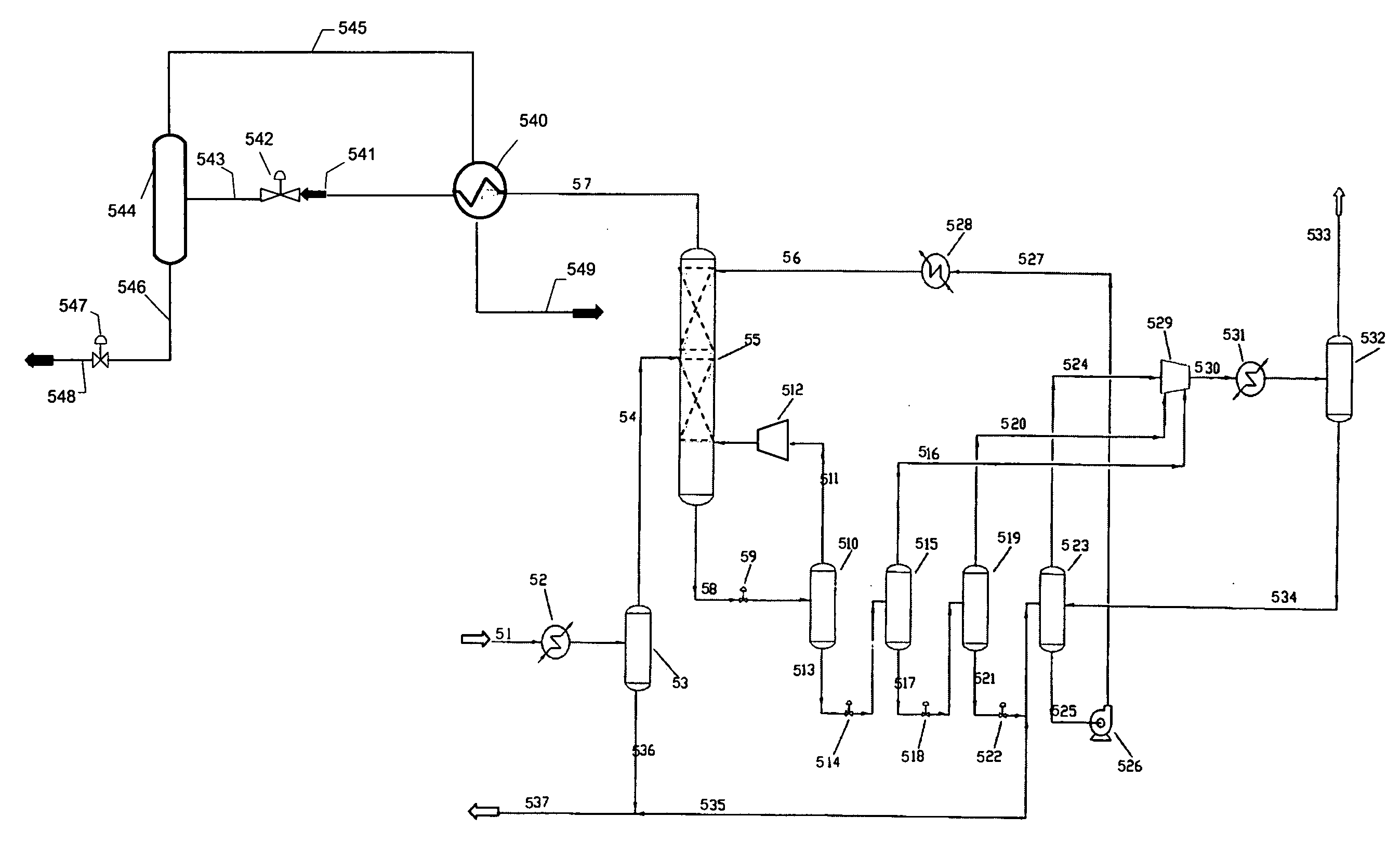
[0051]Use of this process increases recovery of valuable hydrocarbons from the light overhead stream, reduces hydrocarbon emissions when the light component stream would be nitrogen vented to atmosphere, allows use of intermediate weight components in the solvent that improve absorption efficiency as potential emissions are no longer a limitation, allows this recovery at warmer temperatures than prior art and also allows for recovery of these hydrocarbons at pressure higher than prior art that allows for increased flexibility of for use of the recovered liquid hydrocarbons.
[0052]All of the processes depicted in FIGS. 5A through 9 utilize cooling by heat exchange with streams in the purification section, auto-refrigeration cooling by pressure drop, and separation of condensed components from the purified vapor. The valve 557 of FIG. 5B, valve 649 of FIG. 6, valve 854 of FIG. 8, and expander 954 of FIG. 9 are important to allow the separation of components a higher temperature than other processes, allowing the process to meet higher BTU recovery or VOC reduction goals at separator temperatures of −250° F. or higher such as −200° F. or even −175° F. or warmer. Additional variations are possible and are included in this invention disclosure, including reheating the recovered liquid to further cool the incoming vapor, utilizing expanders or hydraulic turbines instead of valves for pressure drop auto refrigeration, using simple pressure regulators in place of pressure control valves, providing one or more additional separators, enabling heavier components to be separated prior to cooling below its freeze point, providing pressure drop auto refrigeration only on the purified separator gas in order to allow the separator to operate at inlet pressure less heat exchange pressure drop only. Operability items and controls are also not indicated in the figures. These can include bypass pipes and controls around heat exchangers, dehydration of feed steam 57 from the absorber in FIG. 5A by molecular sieve or other method when required to prevent freezing or hydrate formation, injection points for methanol for hydrate prevention or thawing of hydrates, bypass lines to allow backflow of warm gas for thawing any hydrates intermittently, line and control valve sizing that can be useful to prevent flow rates that are too high or large vapor flow out the recove

Problems solved by technology

For example, contamination of natural gas with one or more light components is particularly common.
Nitrogen must therefore be removed from natural gas containing more than the specified amount or the natural gas cannot be transported and marketed.
Likewise, removing nitrogen from the plant stream increases the heating value of the remaining hydrocarbon stream and potentially increases the stream's value as a fuel stream.
These heaviest components are those that do not readily vaporize in the flash regeneration of the circulating solvent.

Method used


Image

  • Hydrocarbon recovery and light product purity when processing gases with physical solvents
  • Hydrocarbon recovery and light product purity when processing gases with physical solvents
  • Hydrocarbon recovery and light product purity when processing gases with physical solvents

Examples


example 1

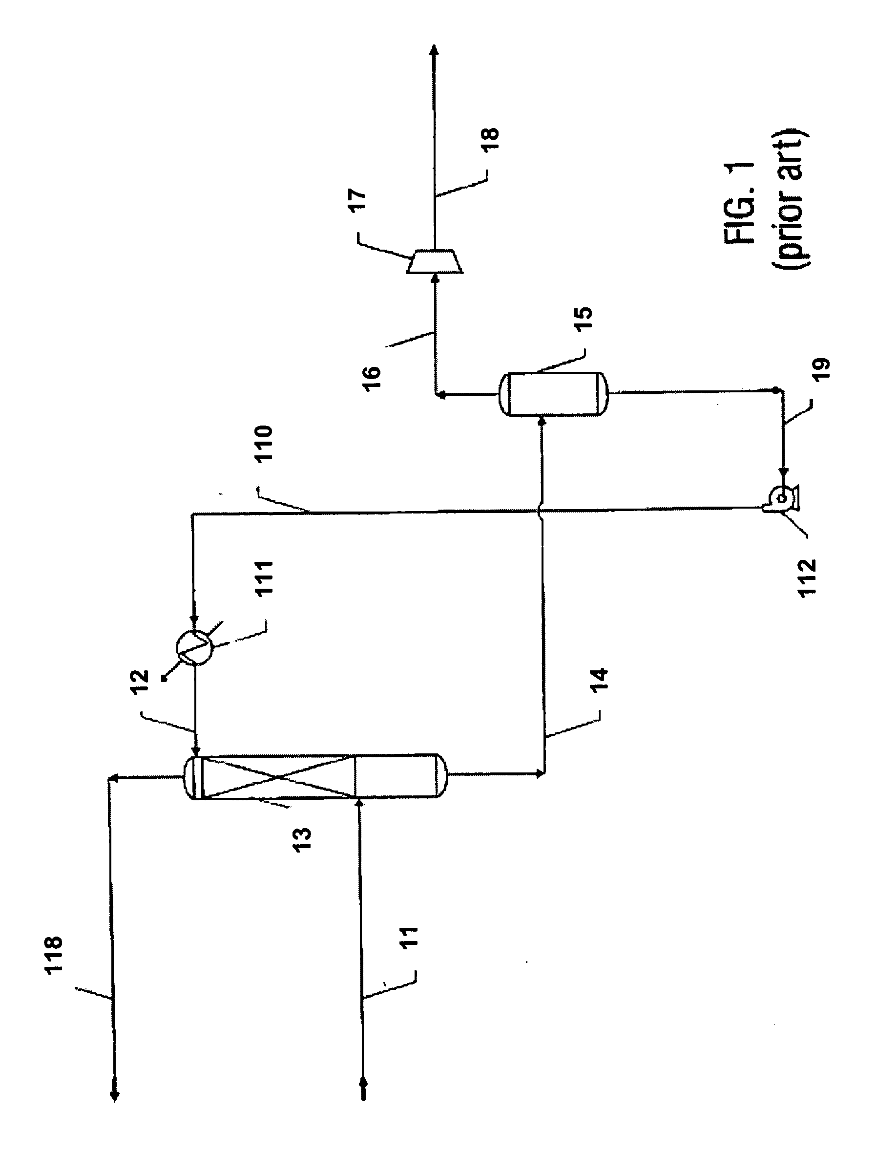
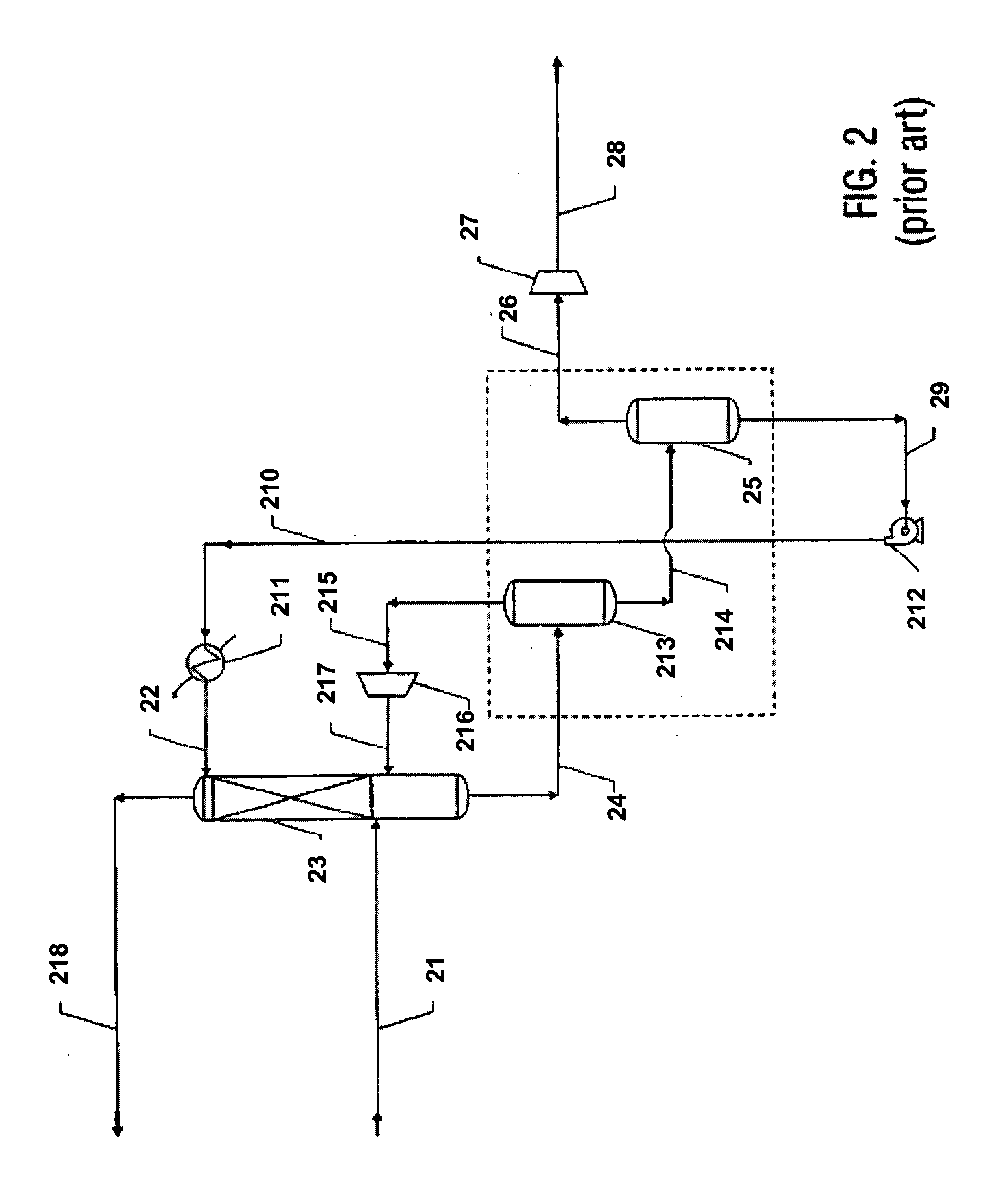
[0054]This example compares the process of the present invention as described in FIG. 5A with the prior art process described in FIG. 3 with regard to their ability to process a gas stream comprising methane and nitrogen and heavier components by absorbing the methane away from the nitrogen in order to produce a methane stream that meets typical pipeline quality for inert content. The comparison is conducted under conditions such that a prior art process according to FIG. 3 utilizes an internal solvent made up of the heavier components of the feed stream, and solvent inventory is controlled by use of a product hydrocarbon gas chiller 331 for solvent recovery. Excess condensed hydrocarbon liquid from the product hydrocarbon gas stream is routed to a stabilizer to produce a separate liquid product.

[0055]The feed gas characteristics used for this example are a flow rate of 10 MMscfd, pressure of 600 psig, temperature of 120° F., and a composition of the following, in mole percent: nitr...

example ii

[0064]This example compares the process of the present invention as described in FIG. 6 with the prior art process described in FIG. 3 and as indicated above in EXAMPLE I, the results of which are shown in Table I above. The absorber overhead product stream cooler, dual pressure reduction, and separator arrangement is added to the process to purify the vent stream and recover additional hydrocarbons. Operating conditions used for this case are as follow: Stream 67, 570 psia and −24° F.; stream 641, 565 psia and −160° F.; streams 643, 646, and 645, 419 psia and −172° F.; stream 650, 145 psia and −200° F.; stream 651, 140 psia and −29° F. Operating pressure of separator 644 is the same as in the original conditions for FIG. 5A above, and VOC content of the vent stream is even lower than use of the process as described by FIG. 5B, while the minimum temperature in the system is −200° F. versus −215° F. in the process of FIG. 5B. The results are indicated in Table III. Compared to the re...

example iii

[0065]This example compares the process of the present invention as described in FIG. 8 with the prior art process described in FIG. 3 and as indicated above in EXAMPLE I, the results of which are shown in Table I above. The absorber overhead stream cooler, dual pressure reduction, absorber separator scheme is added to the process to purify the light component vent stream and recover additional hydrocarbons. Operation of the absorber (item 849 in FIG. 8) at a pressure slightly above the solvent recovery system allows direct flow of the recovered liquids to the solvent recovery system. Operating conditions for this case are as follows: stream 87, 570 psia and −24° F.; stream 841 comprising 95% of stream 87, and stream 846 comprising 5 percent of stream 87; stream 843, 565 psia and −169°; stream 845, 419 psia and −181° F.; stream 848, 419 psia and −31° F.; stream 850, 419 psia and −83° F.; stream 853, 419 psia and −177° F.; stream 855, 200 psia and −200° F.; and stream 856, 195 psia a...


PUM

PropertyMeasurementUnit
Temperatureaaaaaaaaaa

Abstract

A process and apparatus for separating the components of a multi-component gas stream comprising light and intermediate volatility components. The process includes contacting the multi-component gas stream with a lean solvent in an absorber to produce a light component overhead stream and a rich solvent bottoms stream, flashing the rich solvent bottoms stream in at least one reduced pressure stage, recycling the lean solvent to the absorber, heat exchange cooling of the light component overhead stream, using at least one pressure reduction device for auto-refrigeration cooling, vapor / liquid separating the light component overhead stream in a vapor / liquid separator, reheating a vapor product stream from the vapor / liquid separator against the light component overhead stream, and removing the condensed intermediate component liquid from the vapor / liquid separator. The apparatus for separating the components of a multi-component gas stream containing hydrocarbons including an absorption tower containing internal equipment for contacting a feed gas with a lean solvent stream to create an light component overhead stream and a rich solvent bottom stream, a heat exchanger in contact with the light component overhead stream and a purified product stream, a vapor / liquid separator in contact with the light component overhead stream, and a pressure reduction device in contact with the light component overhead stream.

Description

PRIORITY[0001]This application claims the benefit under 35 U.S.C. 119(e) of U.S. Provisional Application Ser. No. 60 / 925,585, filed Apr. 20, 2007, the entire contents of which are incorporated herein by reference.FIELD OF THE INVENTION[0002]The invention relates to the field of chemical processing and, more specifically, to the processing of hydrocarbon gas streams. In particular, a method and apparatus for separating the components of a hydrocarbon gas stream is disclosed.BACKGROUND OF THE INVENTION[0003]Many hydrocarbon gases such as natural gas, cracked gas, or refinery off gas contain one or more light components that either contaminate the main gas or that are themselves valuable if they can be separated from the main gas stream. Such light gases include nitrogen, helium, and hydrogen. A number of economic considerations make it desirable to separate these light gases from a hydrocarbon gas stream.[0004]For example, contamination of natural gas with one or more light components...

Claims


Application Information

Patent Timeline
IPC IPC(8): F25J3/08F25J3/00
CPCF25J3/0209F25J3/0233C07C7/005C10L2290/48C10L2290/46F25J3/0257F25J2200/02F25J2200/04F25J2205/02F25J2205/04F25J2205/50F25J2245/02F25J2270/04B01D53/14C07C7/11C10G5/04B01D53/002B01D53/1487B01D2252/205B01D2256/245B01D2257/102B01D2257/108C10L2290/10C10L2290/06C10L3/101C10L3/105C10L2290/541C07C9/04
Inventor MOWREY, EARLE R.GASKIN, THOMAS K.
Owner ADVANCED EXTRACTION TECH
Learn More