Motor control apparatus

a motor control and motor technology, applied in the direction of electric controllers, electronic commutators, instruments, etc., can solve the problems of deterioration of the control system, error of 360° (edeg) or 18° (edeg) period in terms of electrical angle, etc., to prevent oscillation, avoid excessive processing, and easily estimate the rotational period

Inactive Publication Date: 2008-10-30
HONDA MOTOR CO LTD
View PDF4 Cites 29 Cited by
  • Summary
  • Abstract
  • Description
  • Claims
  • Application Information

AI Technical Summary

Benefits of technology

[0032]In the motor control apparatus according to the fifth aspect of the present invention, excessive execution of processing to synchronize the control period with the rotational period of the motor can be prevented.
[0033]In the motor control apparatus according to the sixth aspect of the present invention, it is possible to prevent the control period from reaching the response threshold of the various components and control apparatus, etc., when the rotational period of the motor has changed.
[0034]In the motor control apparatus according to the seventh aspect of the present invention, the period Tc of the carrier signal is set in the specified equation (Tc=(T−k×Δt) / N), based on a specified coefficient k which is equal to or less than one and greater than zero. Thus, for example, by setting the specified coefficient k to be less than 1 when the rotational period of the motor varies, it is possible to suitably set the control gain when converging the phase difference Δt to zero, and to prevent oscillation, etc. in the phase difference Δt.
[0035]In the motor control apparatus according to any one of the eighth through eleventh aspects of the present invention, it is possible to easily estimate the rotational period with good accuracy when the angular velocity of the motor rotation angle is changing, without requiring complicated analysis processing.
[0036]Further, in the motor control apparatus according to the twelfth aspect of the present invention, it is possible to suitably increase the output of a claw pole type motor, while decreasing the size thereof.

Problems solved by technology

However, when operating a motor at high frequency, the stability of the control system deteriorates due to errors in the detection of the rotation phase and higher harmonic components in the electrical current passing through the motor.
As a result, when the control period approaches the period of the higher harmonic components, sub-harmonic variation and regular off-set occurs, leading to a deterioration in the control system.
Due to errors of the detection system or the like, a resolver or other such angle sensor, which outputs a pulse in accordance with the rotation angle of the motor, will generates an error of a 360° (edeg) or 18° (edeg) period in terms of electrical angle.
Thus, when the control period approaches the 360° (edeg) period in terms of electrical angle, sub-harmonic variation and regular off-set occur, problematically leading to a deterioration in the control system.

Method used


Image

  • Motor control apparatus
  • Motor control apparatus
  • Motor control apparatus

Examples


Embodiment Construction

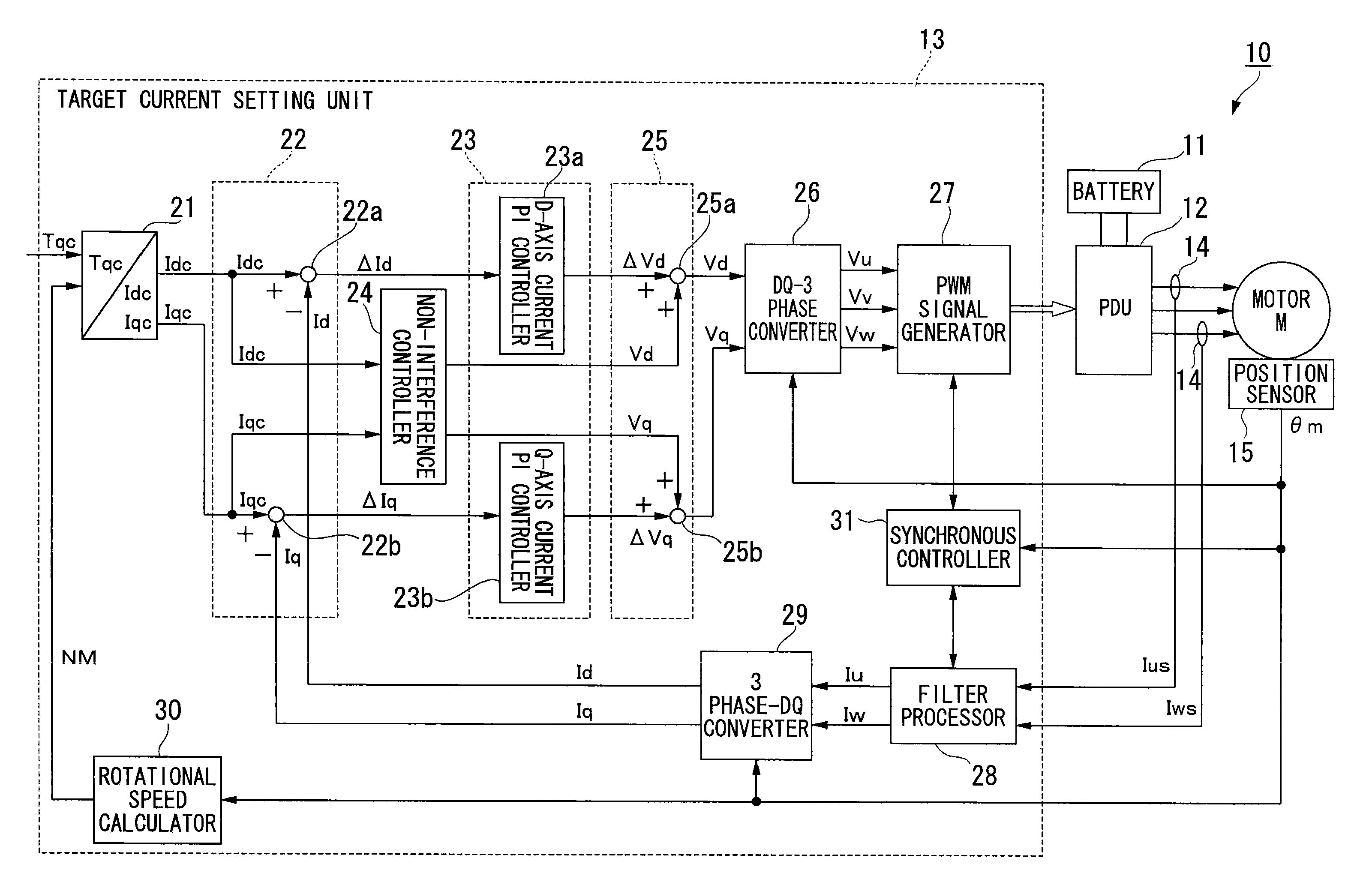
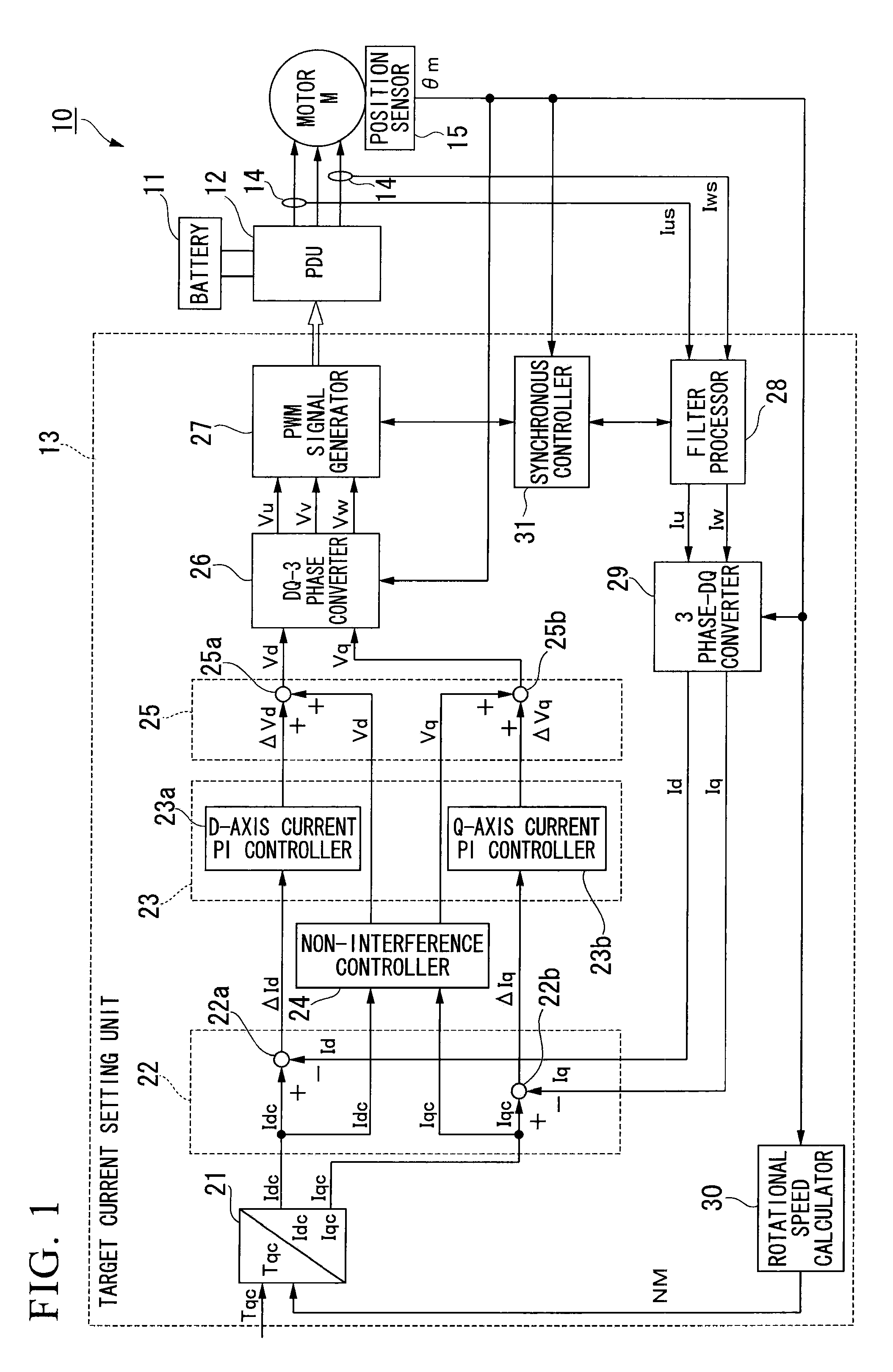
[0054]Preferred embodiments of the motor control apparatus according to the present invention will now be explained with reference to the accompanying figures.

[0055]A motor control apparatus 10 according to this embodiment is provided with a power drive unit (PDU) 12, which employs a battery 11 as a direct current source, and a controller 13, as shown in FIG. 1. This motor control apparatus 10 is installed in a hybrid vehicle or electric vehicle that is equipped with a motor M as the drive source, for example.

[0056]In this motor control apparatus 10, the power drive unit (PDU) 12 receives control commands output from the controller 13 and carries out the driving and regenerating operations of the motor M.

[0057]The PDU 12 includes, for example, a PWM inverter by pulse width modulation (PWM) having a bridge circuit with a plurality of switching elements of transistors connected by bridges, and the high voltage battery 11 for supplying and receiving electric energy to and from the moto...


PUM


Abstract

A motor control apparatus provided with an inverter for successively commutating the current to a motor using a PWM signal; a PWM signal generating device for generating the PWM signal using a carrier signal; a rotational state quantity sensor for detecting a rotational state quantity; a phase difference detecting device for detecting the phase difference between the carrier signal and the rotational period based on the rotational state quantity; a frequency setting device for setting a frequency of the carrier signal to a value in accordance with a multiplier for one period in terms of electrical angle of the rotational period of the motor, when the rotational frequency is equal to or greater than a specified frequency and the phase difference is equal to or less than a specified value; and a synchronizing device for synchronizing a control period of the carrier signal to the rotational period.

Description

BACKGROUND OF THE INVENTION[0001]1. Field of the Invention[0002]The present invention relates to a motor control apparatus.[0003]Priority is claimed on Japanese Patent Application No. 2007-114047, filed Apr. 24, 2007, the content of which is incorporated herein by reference.[0004]2. Description of Related Art[0005]There has been a desire for higher frequency motors in order to increase motor output while decreasing motor size.[0006]By increasing the pairs of poles of a motor, for example, there is a decrease in the circumferential width of the teeth of the stator and an accompanying reduction in the width of the back yoke that supports the teeth. As a result, the control frequency of the motor becomes higher accompanying the reduction in motor size. In addition, the torque that a motor is capable of outputting increases and decreases in accordance with motor size. Thus, by increasing the revolutions that can be achieved, it is possible to increase output (i.e., product of torque and...

Claims


Application Information

Patent Timeline
Patent Type & Authority Applications(United States)
IPC IPC(8): H02P27/08H02P6/06H02P6/08H02P6/16H02P6/17H02P6/28
CPCH02P21/0035H02P21/06H02P6/183H02P21/22
Inventor IMAI, NOBUYUKIMURAYAMA, YOSHINARIINOUE, JUNJI
Owner HONDA MOTOR CO LTD
Why Eureka
Try Eureka