
Water Distillation System

a technology of water distillation system and water distillation temperature, which is applied in the direction of auxilaries, water/sludge/sewage treatment, vessel construction, etc., can solve the problems of further reduction in efficiency, congested sea water, and low distillation temperature to kill bacteria

Inactive Publication Date: 2008-11-13
GREGORY MARK PAXTON +1
View PDF15 Cites 17 Cited by
  • Summary
  • Abstract
  • Description
  • Claims
  • Application Information

AI Technical Summary

Benefits of technology

[0027]Where possible, the heat storage arrangement is configured to consume energy supplied from at least one external source and to store the consumed energy in the heat generating source. Preferably, said at least one external source is / are arranged to supply solar energy, and / or electric energy and / or heat energy. Advantageously, the heat storage arrangement is configured to consume energy supplied at predetermined time periods. Said time periods may correspond to off-peak periods set by relevant authorities. The energy may be locally produced, e.g. methane from mining operations or a pipeline gas such as ethylene or a liquid hydrocarbon, e.g. kerosene and / or off peak electrical energy. For some applications the gas may be hydrogen from electrolysed water. The heat storage arrangement is there to enable the Carnot cycle to supply the requisite heat and the principles of that cycle apply. It is preferred that the system further includes a furnace or boiler or used jet engine arranged to complement the heat generating source as it has a heat output of the appropriate order and is economical to install. Where the heat generating source is arranged to absorb heat from a jet engine. The hot exhaust from the jet engine is directed through an insulated duct provided with a number of finned carbon steel tubes arranged across the duct. As the hot exhaust gas (>650° C.) passes through the heat exchange arrangement, heat is absorbed into the heat storage arrangement and feed water in the form of sea water or other source water in the brine circuit tubes is heated under pressure to a predetermined temperature above the predetermined boiling point of the feed water.
[0029]The second heat exchanger is used to preheat the feed water before the relatively high temperature first heat exchanger. To avoid the build up of mineral deposits in the heat exchanger tubes a magnetic induction pump may be used to re▴circulate the water at high velocities through the high temperature heat exchanger ensuring that the temperature rise of the water is no more than 2° C. at each pass of the water. This will ensure that there will be the minimum build▴up of solid lining in the heat exchanger water tubes.
[0030]Feed water is normally drawn into said one or each flashing stage by a pump that is controlled by a Digital Control System (DCS) using a Variable Frequency Drive (VFD) to dynamically control the temperature, flow and pressure of the process utilising Proportional and Integral, Differential (P and ID) control. This allows the automation of the whole system without any intervention at all or with only little intervention, save for maintenance.

Problems solved by technology

However this method also has a number of disadvantages including:1. Very inefficient as indirect methods to heat the sea water are typically used;2. At high temperatures any solids in the sea water will congeal.
The congealed solids are deposited on the surface of the heat exchanger causing further reduction in efficiency.
The major drawback with this system is that the distillation temperature is too low to kill bacteria and ultra violet lamp generated ozone is usually needed to kill bacteria in the distilled water.
It is also not suitable for large scale applications due to the difficulty of maintaining the distillation chamber at below atmospheric pressures.
This method relies very much on the efficiency of the pumps that drive the R.O. system and by their nature pumps are very inefficient users of energy.

Method used


Image

  • Water Distillation System
  • Water Distillation System

Examples


Embodiment Construction

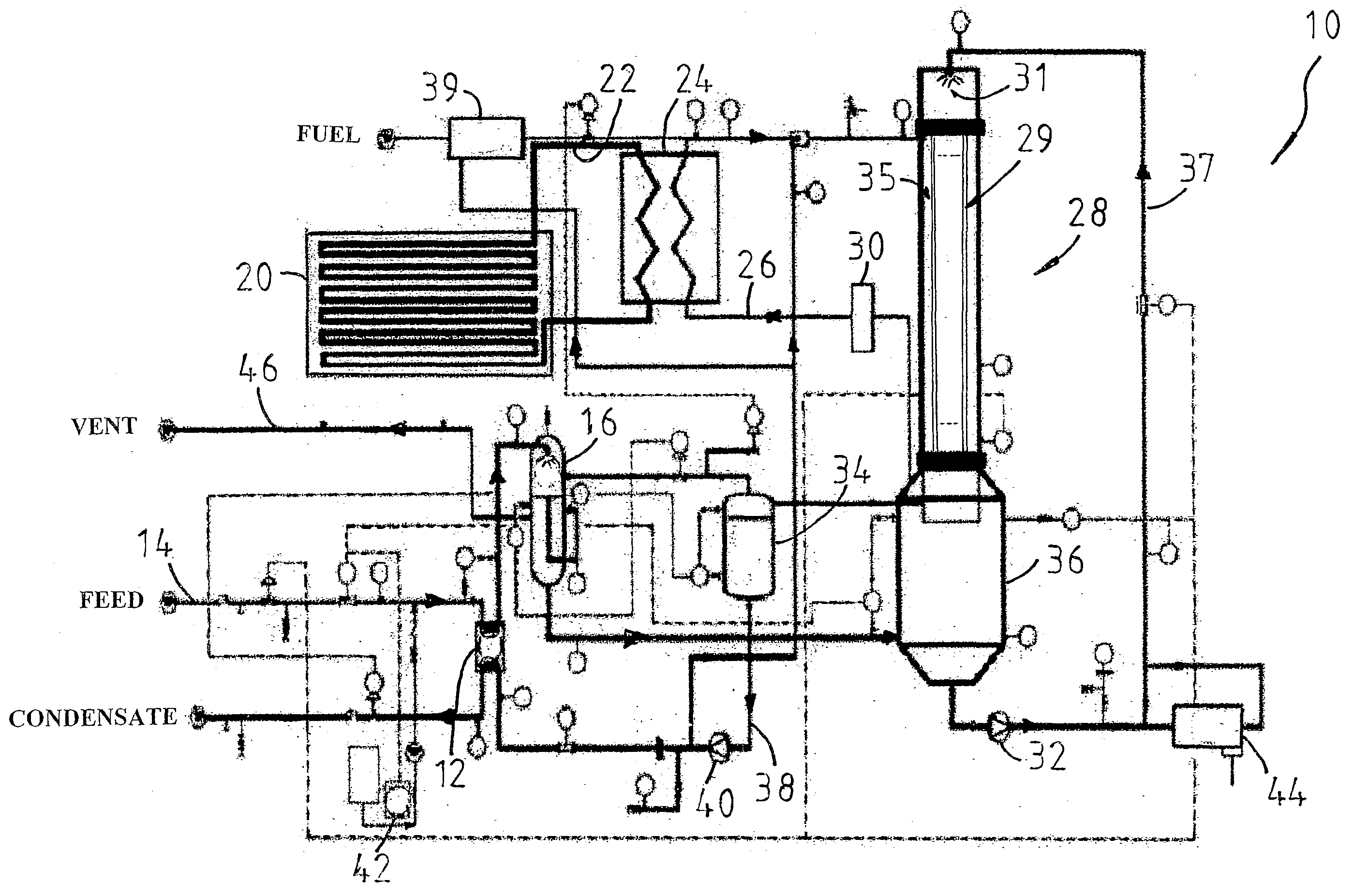
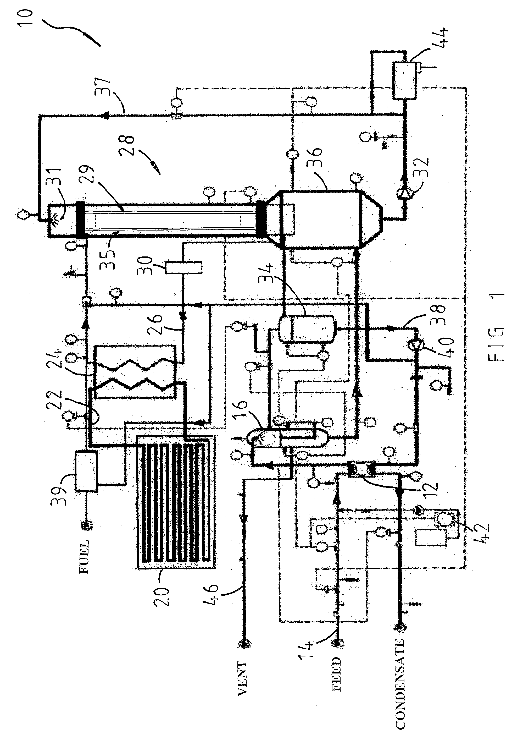
[0045]Referring to FIG. 1, the embodiment of the water distillation system 10 as shown has a secondary heat exchanger 12 arranged to receive feed water flowing in a feed water line 14 that is connected to a feed water source referred to as “FEED” such as a salt water tank. The feed water from the secondary heat exchanger 12 is conveyed to a deaerator 16 and ejected thereat as a spray. Undesired gases in the feed water are released to atmosphere through line 46 and “VENT”. Deaerated water is then transferred to a reservoir 36 in a flashing stage 28. It should be noted that while one flashing stage 28 is described and shown for this embodiment, a plurality of flashing stages can be incorporated into the system 10 according to the present invention.

[0046]The system 10 also has a heat storage arrangement 20 which in this embodiment is in the form of an energy storage vessel and it uses off-peak electricity as energy source for charging energy storing media such as graphite in the storag...


PUM


Abstract

A system for distilling sea or brackish water includes a feed water arrangement for supplying feed water from a feed water source to one or more flashing stages. Each flashing stage has a water flash evaporator for vaporizing at least part of the water therein, and a condenser for receiving the vapour and converting at least a part of the vapour into distilled water. A heat storage arrangement provided with a heat generating source for storing heat energy is used to heat a fluid medium flowing through it. A heat exchange arrangement receives the hot fluid medium and transfers heat to a stream of vapour flowing under pressure from each flashing stage. The vapour leaving the heat exchange arrangement being at a raised temperature is arranged to be condensed into water at the condenser and to transfer some of its latent heat to the evaporator.

Description

TECHNICAL FIELD OF THE INVENTION[0001]THIS INVENTION relates to a water distillation system for recovering potable water from sea water or any organically or mineral polluted water source using a heat source from a heat generating apparatus such as a heat storage system.BACKGROUND OF THE INVENTION[0002]Methods for sea water de-salination have been proposed in a number of different technologies. Two major methods are described here as examples:(a) Distillation Method[0003]One form of this method involves raising the temperature of sea water at atmospheric pressure above 100° C. to produce steam. The steam is then distilled using either ambient air or water as the cooling medium to condense the steam back to pure water. This method has the following advantages:[0004]1. Most bacteria are killed off as the water temperatures are above 65° C.;[0005]2. Systems are easily monitored due to visible boiling taking place;[0006]3. Principal of operation is easy to comprehend so little personnel...

Claims


Application Information

Patent Timeline
IPC IPC(8): C02F1/06
CPCB01D1/0041B01D1/12B01D3/42C02F1/04C02F1/06C02F1/16Y10S159/16Y10S159/901Y10S203/08
Inventor PAXTON, GREGORY MARK
Owner GREGORY MARK PAXTON
Learn More