Semiconductor radioactive ray detector, radioactive ray detection module, and nuclear medicine diagnosis apparatus

Inactive Publication Date: 2008-11-13
HITACHI LTD
View PDF4 Cites 8 Cited by
  • Summary
  • Abstract
  • Description
  • Claims
  • Application Information

AI Technical Summary

Benefits of technology

[0011]In the semiconductor radioactive ray detector according to the present invention, unlike the conventional technology, a conductive adhesive agent, which is a rigid conductive adhesive noncompliant to thermal stress (with a Young's modulus from 350 MPa to 1000 MPa), is used to improve electric conductivity of a metallic filler contained in the conductive adhesive agent and also to avoid distortion of a signal passing therethrough. Furthermore, in the semiconductor radioactive ray detector according to the present invention, the metallic members whose linear expansion coefficient is close to that of the plate-like element of cadmium telluride as a main material of the semiconductor radioactive ray detector, namely in the range from 5×10⁻⁶/° C. to 7×10⁻⁶/° C., is used, so that the possibility of generation of thermal stress in the plate-like element of cadmium telluride and the electrode plate can be minimized. Because of these features, it is possible to obtain a semiconductor radioactive ray detector with the improved gamma ray detection sensibility and also with the elevated higher energy resolution and time precision.
[0012]F

Problems solved by technology

When a volume of the CdTe portion is made larger, the performance, such as the energy resolution, may disadvantageously decrease.
When the percentage of recombining and disappearing of carriers is high, a quantity of electric charge cannot accurately be measured.
Furthermore, when the volume is larger, a period of time required for movement of carriers becomes longer, so that the electric charge moves for a long time, and the time precision for identifying-a point of time when gamma rays enter is deteriorated.
Namely, when the time precision is low, gamma rays cannot be identified discretely, and the direction in which the gamma rays enter cannot be det

Method used


Image

  • Semiconductor radioactive ray detector, radioactive ray detection module, and nuclear medicine diagnosis apparatus
  • Semiconductor radioactive ray detector, radioactive ray detection module, and nuclear medicine diagnosis apparatus
  • Semiconductor radioactive ray detector, radioactive ray detection module, and nuclear medicine diagnosis apparatus

Examples


Example

Embodiment 1

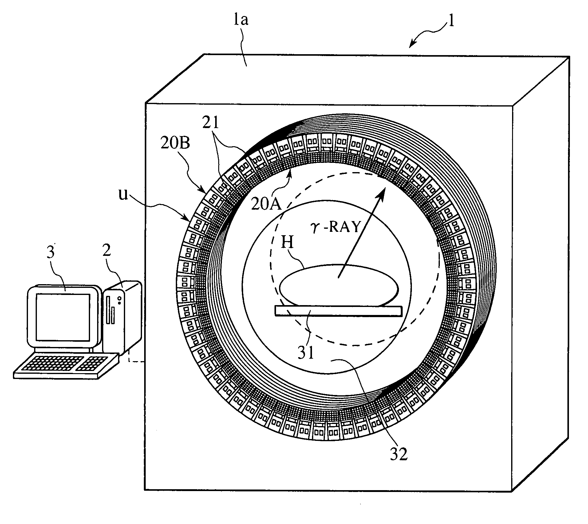
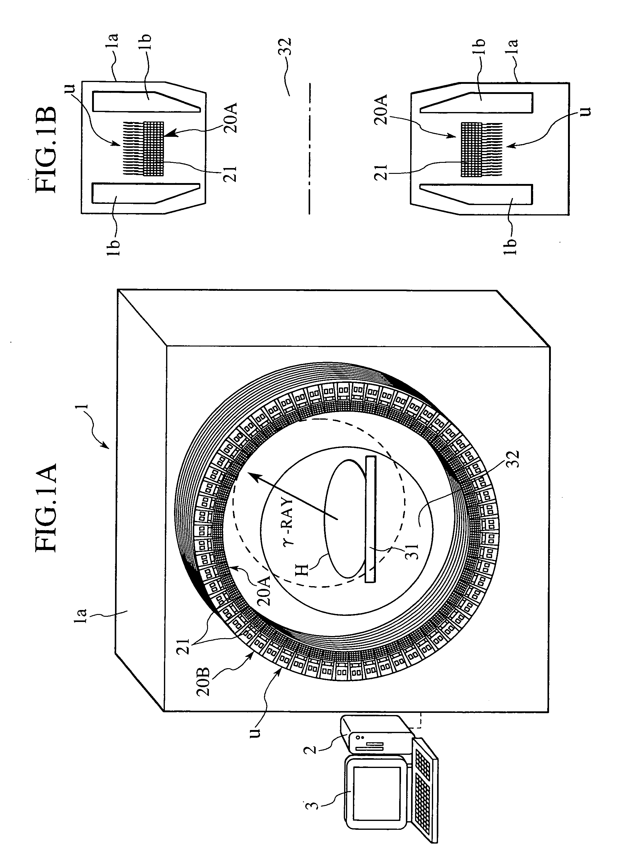
[0033]The PET equipment according to the present embodiment includes, as shown in FIG. 1A, PET equipment 1, a bed 31 for supporting a subject (a person to be examined) H, a data processor (a computer or the like) 2, and a display unit 3. The PET equipment 1 has a number of unit substrates U positioned in the circumferential direction as shown in FIGS. 2A and 2B. In the PET equipment 1, the subject H is laid on the bed 31 movable in the longitudinal direction, and moved into a column-shaped measuring space 32 surrounded by the unit substrates U.

[PET Equipment]

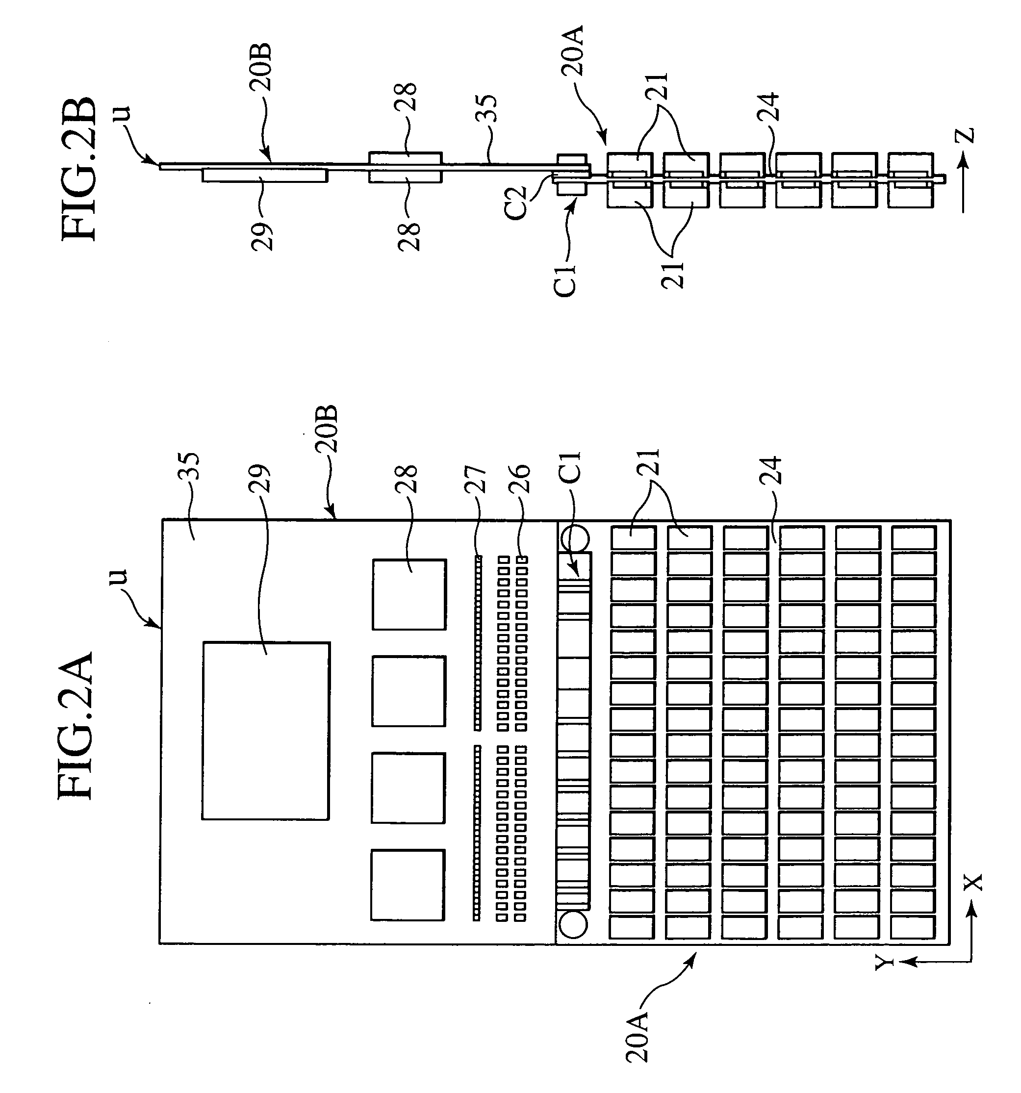
[0034]The PET equipment 1 includes a number of unit substrates U positioned in the circumferential direction surrounding the measuring space 32 in which the bed 31 is moved. A plurality of the unit substrates U are positioned in the longitudinal direction of the bed 31 (the axial direction of the measuring space 32). The unit substrate U includes, as shown in FIGS. 2A and 2B, a radioactive ray detection module (herei...

Example

Embodiment 2

[0088]The detector used in the PET equipment according to another embodiment of the present invention is described below. The detector according to this embodiment can be used in place of the detector 21 which is used in the PET equipment 1 shown in FIG. 1, and as shown in FIG. 9, a detector 40 has conductive members 41a, 42a each having a form like an elongated plate. An incoming direction of a radioactive ray is X axis direction. Portions of the PET equipment according to an embodiment 2 other than the detector 40 are the same as those of the PET equipment according to the first embodiment described above and shown in FIG. 1.

[0089]The conductive members 41a, 42a each has an elongated plate-like form and can be inserted into sockets 43, 44 provided on the wiring board 24, and are connected to terminals not shown and formed in the sockets 43, 44. Also in this detector 40, the conductive members 41a, 42a are provided between the same types of electrodes facing against eac...

Example

[0092]A detector adapted to use in the PET equipment according to a third embodiment of the present invention is described below. The detector according to this embodiment can be used in places of the detector 21 shown in FIG. 1 which is used in the PET equipment 1, and has the detecting elements 211 and the conductive members 51a, 52a horizontally laminated alternately on the wiring board 24 as shown in FIG. 10. An incoming direction of a radioactive ray is X axis direction. Portions of the PET equipment according to this embodiment other than a detector 50 are the same as those of the PET equipment according to the embodiment 1 shown in FIG. 1.

[0093]The detector 50 is adhered to an electrode base 53 mounted and attached to a surface of the wiring board 24 with a conductive adhesive agent (not shown like in the first embodiment). The electrode base 53 is made of an iron-nickel alloy, and for instance, the 42% alloy (with the Fe content of 58% and Ni content of 42%) can be used for ...


PUM


Abstract

The present invention provides a semiconductor radioactive ray detector having the excellent energy resolution or time precision, a radioactive detection module, and a nuclear medicine diagnosis apparatus. The semiconductor radioactive ray detector has a structure in which plate-like elements made of cadmium telluride and conductive members are alternately laminated and the plate-like element made of cadmium telluride and the conductive member are adhered to each other with a conductive adhesive agent, and the Young's modulus of the conductive adhesive agent is in the range from 350 MPa to 1000 MPa, while the conductive members are made from a material with the linear expansion coefficient of the conductive members in the range from 5×10⁻⁶/° C. to 7×10⁻⁶/° C.

Description

BACKGROUND OF THE INVENTION[0001]The present invention relates to a semiconductor radioactive ray detector having a semiconductor radioactive ray detecting element, a radioactive ray detection module, and a nuclear medicine diagnosis apparatus using the radioactive ray detection module.[0002]Equipment based on the radioactive ray measuring technique has been becoming more and more widespread. In particular, the tendency is remarkable in the field of nuclear medicine, and the representative equipment include positron emission tomographic equipment (PET equipment), single photon emission tomographic equipment (SPECT equipment), and a gamma camera. A radioactive ray detector generally used in the equipment is a combination of a scintillater and a photoelectric multiplier. A scintillater emits light when radioactive rays enter, and the weak light is amplified by the photoelectric multiplier for detection of radioactive rays. Instead of the scintillater, a semiconductor radioactive ray d...

Claims


Application Information

Patent Timeline
IPC IPC(8): G01T1/24
CPCG01T1/249G01T1/2985A61B6/037G01T1/244G01T1/243
Inventor SEINO, TOMOYUKIYANAGITA, NORIHITOTAKAI, TOSHIAKIYORITA, CHIKOMATSUSHIMA, NAOKI
Owner HITACHI LTD
Why Eureka
Try Eureka