
Cathode active material for lithium secondary battery

Pending Publication Date: 2021-09-16
LG ENERGY SOLUTION LTD
View PDF0 Cites 0 Cited by
  • Summary
  • Abstract
  • Description
  • Claims
  • Application Information

AI Technical Summary

Benefits of technology

The present invention provides a positive electrode active material for a lithium secondary battery that includes a coating layer containing carbon nanostructure and iron oxyhydroxynitrate. This material helps to prevent the problems caused by lithium polysulfide and improves electrical conductivity. The resulting battery has high capacity, stable sulfur loading, improved stability, high charging / discharging efficiency, and improved lifetime characteristics.

Problems solved by technology

However, the lithium secondary battery, which has the best characteristics among the secondary batteries known to date, also has several problems in being actively used in transportation vehicles such as electric vehicles and PHEVs, and among them, the biggest problem is the limit in capacity.
Among them, since the capacity of the battery is determined by the positive and negative electrode materials, the lithium ion secondary battery is limited in capacity due to the material limitations of positive and negative electrodes.
One of the biggest constraints to the sale of electric vehicles is that the distance that can be traveled after charging once is much shorter than those of ordinary gasoline engine vehicles.
The limitation of the capacity of such a lithium secondary battery is difficult to be completely solved due to the structure and material constraints of the lithium secondary battery despite of much effort.
One of the main problems of the lithium-sulfur battery revealed to date is that since sulfur has an electrical conductivity of about 5.0×10⁻¹⁴ S / cm and thus is close to nonconductor, electrochemical reaction at the electrode is not easy, and due to the very large overvoltage, the actual discharging capacity and voltage are far below the theoretical value.
Early researchers tried to improve the performance by methods such as mechanical ball-milling of sulfur and carbon or surface coating with carbon, but there was no substantial effect.
Another major problem associated with the lithium-sulfur battery is the dissolution of lithium polysulfide into the electrolyte, which is the intermediate product of sulfur generated during discharging.
When this reaction occurs, not only the reversible positive electrode capacity is greatly reduced but also the dissolved lithium polysulfide diffuses into the negative electrode and causes various side reactions.
The lithium polysulfide causes a shuttle reaction especially during the charging process, and as a result, the charging capacity is continuously increased, and the charging / discharging efficiency is rapidly deteriorated.
Although such efforts are under way, these methods are not only somewhat complicated, but also have a problem that the amount of sulfur that can be added, which is an active material, is limited.

Method used


Image

  • Cathode active material for lithium secondary battery
  • Cathode active material for lithium secondary battery
  • Cathode active material for lithium secondary battery

Examples


example 1

Manufacturing of Lithium-Sulfur Battery

[0121]88 parts by weight of the positive electrode active material prepared in the above Preparation Example, 5 parts by weight of VGCF (Vapor Grown Carbon Fiber) as an electrically conductive material, and 7 parts by weight of lithiated polyacrylamide (LiPAA) / polyvinylalcohol (PVA) (LiPAA / PVA: 6.5:0.5) as a binder were added to de-ionized water (DIW) as a solvent, and mixed to prepare a slurry composition for positive electrode active material.

[0122]Subsequently, the prepared slurry composition was coated on a current collector (Al Foil, 20 μm) and dried at 50° C. for 12 hours to prepare a positive electrode for a lithium-sulfur battery. At this time, the loading amount was 3.5 mAh / cm2, and the porosity of the electrode was 60%.

[0123]Thereafter, a coin cell of a lithium-sulfur battery comprising the positive electrode manufactured according to the above, lithium metal as a negative electrode, a separator and an electrolyte. A mixed solution co...

experimental example 1

Scanning Electron Microscope (SEM) Analysis

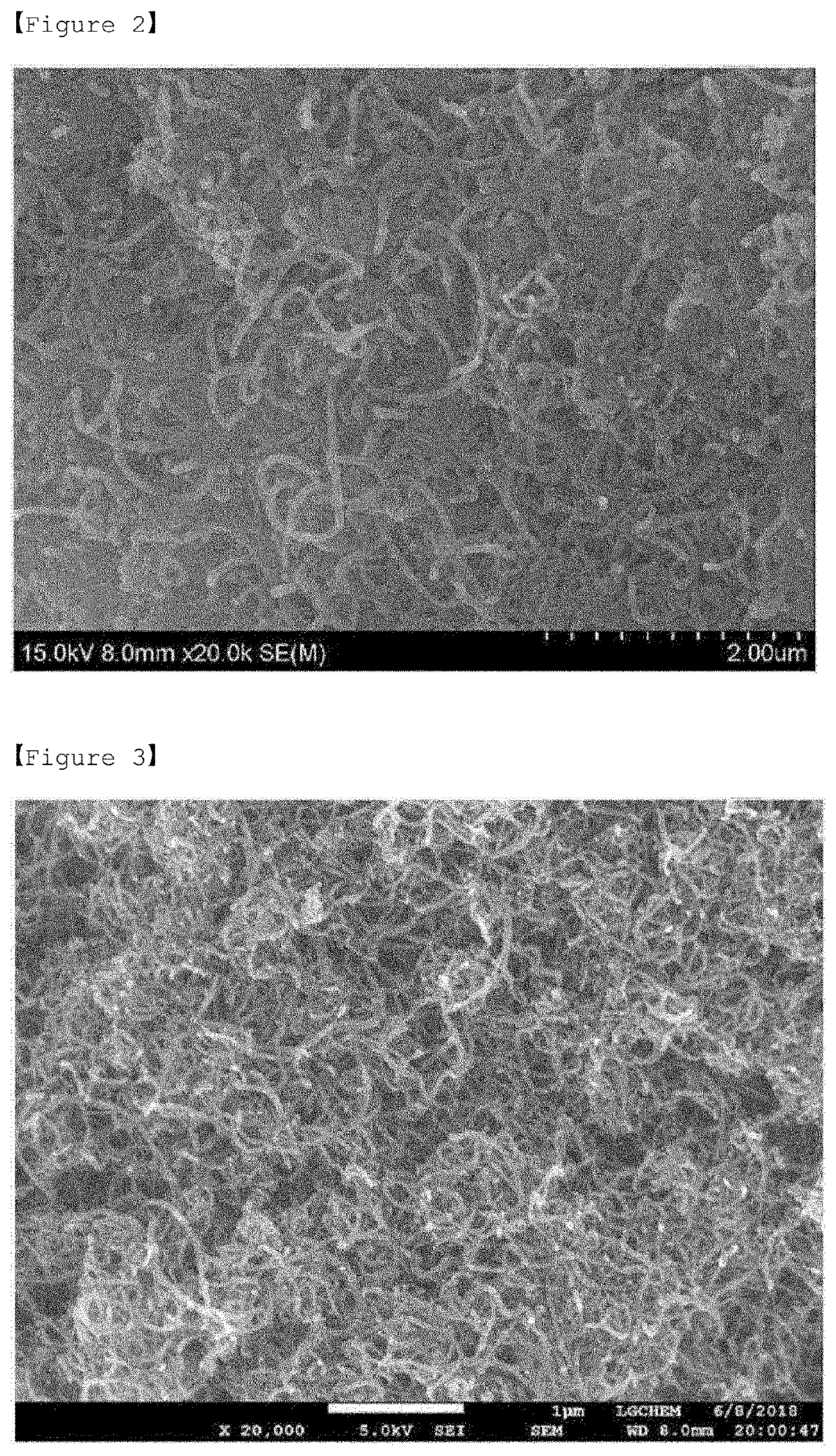
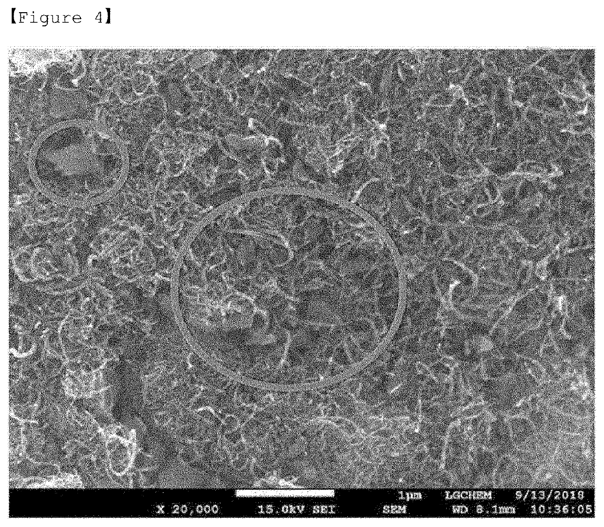
[0126]The positive electrode active materials according to Preparation Example and Comparative Preparation Examples 1 to 2 were each subjected to SEM analysis (S-4800 FE-SEM from Hitachi company) at a magnification of 20 k.

[0127]FIGS. 2 to 3 are SEM images of the positive electrode active materials according to Comparative Preparation Examples 1 and 2, respectively, and FIG. 4 is a SEM image of the Preparation Example.

[0128]In the case of FIG. 2 according to Comparative Preparation Example 1 of the present invention, it was confirmed that the coating layer is not formed on the positive electrode active material, and thus the surface of the sulfur-carbon composite is exposed.

[0129]In the case of FIG. 3 according to Comparative Preparation Example 2 of the present invention, it was confirmed that although the surface of the sulfur-carbon composite was not exposed due to the coating layer of carbon nanotubes, iron oxyhydroxynitrate according t...

experimental example 2

X-Ray Diffraction (XRD) Analysis

[0131]The iron oxyhydroxynitrate prepared in Preparation Example was subjected to XRD analysis (D4 Endeavor from Bruker company).

[0132]FIG. 5 is a graph showing the XRD analysis of the iron oxyhydroxynitrate prepared in Preparatory Example.

[0133]Referring to FIG. 5, the XRD peaks of the (310) and (520) planes were 2θ=35.2±0.2° and 61.3±0.2°, respectively, and thus it was confirmed that iron oxyhydroxynitrate of the pure phase according to the present invention was prepared.


PUM


Abstract

A positive electrode active material for a lithium secondary battery, including a sulfur-carbon composite and a coating layer located on a surface of the sulfur-carbon composite and including a carbon nanostructure and iron oxyhydroxynitrate.

Description

TECHNICAL FIELD[0001]The present invention relates to a positive electrode active material for a lithium secondary battery comprising a coating layer.[0002]The present application claims the benefit of priority based on Korean Patent Application No. 10-2019-0016495 filed on Feb. 13, 2019, all the contents of which are incorporated herein by reference.BACKGROUND ART[0003]Secondary batteries have become important electronic components for portable electronic devices since the 1990s as an electric storage device capable of continuous charging and discharging unlike the primary battery which can only discharge once. In particular, since a lithium ion secondary battery was commercialized by Sony Corporation in Japan in 1992, it has led to the information age as a key component of portable electronic devices such as smart phones, digital cameras, and notebook computers.[0004]In recent years, lithium ion secondary batteries are rapidly growing in demand from electric sources of cleaner and...

Claims


Application Information

Patent Timeline
IPC IPC(8): H01M4/62H01M4/587H01M4/36H01M10/052
CPCH01M4/625H01M4/587H01M2004/021H01M10/052H01M4/362H01M4/38H01M4/62Y02E60/10H01M4/366H01M4/13C01B17/00C01P2004/03C01B32/15H01M4/624H01M2004/028
Inventor HAN, SUENGHOONKIM, EUI TAE
Owner LG ENERGY SOLUTION LTD
Learn More