Evanescent wave multimode optical waveguide and sensor with high mode coupling

a multi-mode optical waveguide and high-mode coupling technology, applied in the field of chemical sensors, can solve the problems of difficult and reliable quantification of the concentration of absorbent species, and achieve the effect of less sensitive to vibration, movement and bending

Active Publication Date: 2008-12-04
INSTITUT NATIONAL D'OPTIQUE
View PDF5 Cites 14 Cited by
  • Summary
  • Abstract
  • Description
  • Claims
  • Application Information

AI Technical Summary

Benefits of technology

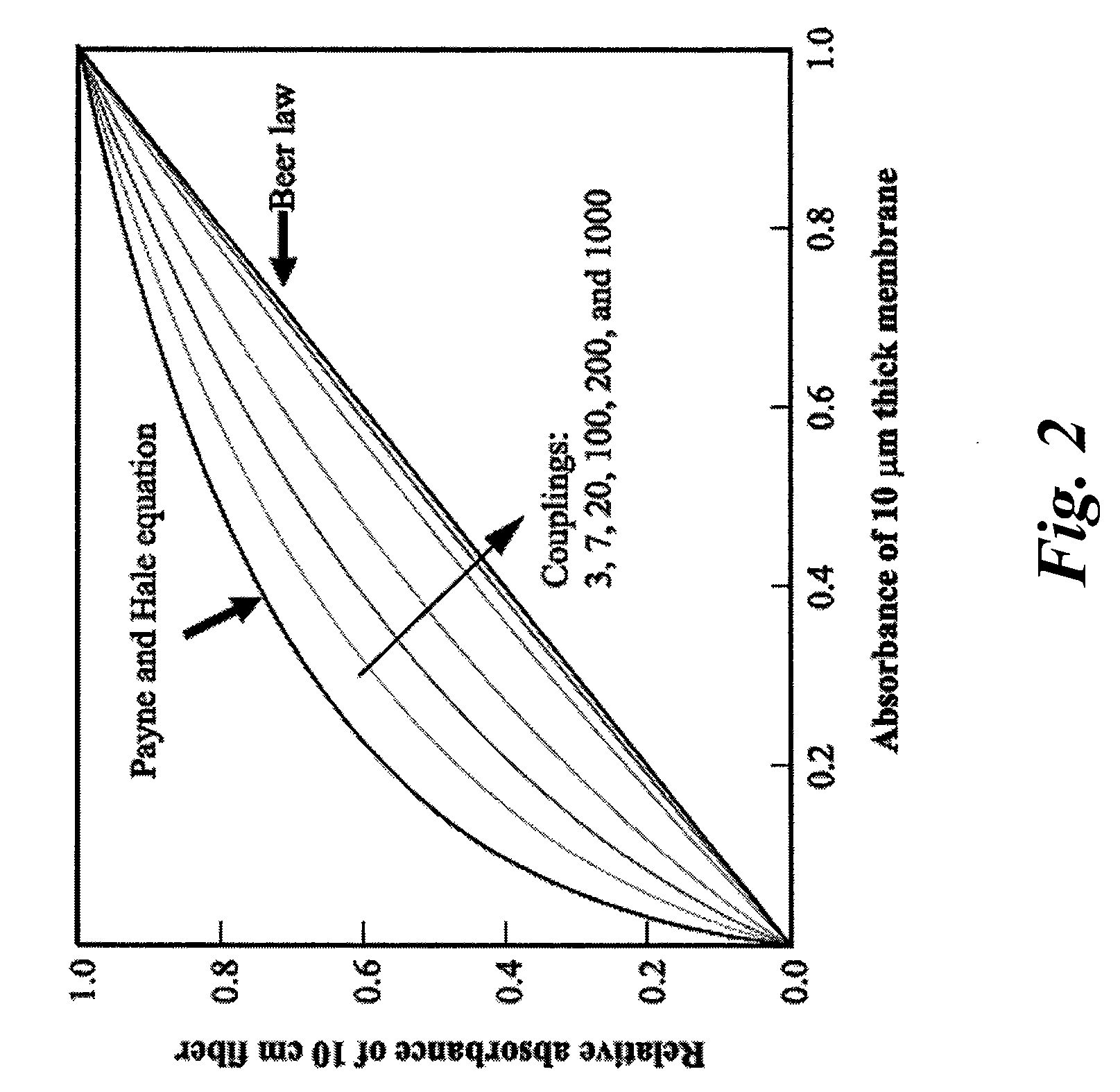
[0016]Moreover, a strong mode coupling results in an absorbance independence on the light injection conditions at the input of the waveguide, which provides stability of the sensor to light injection conditions between the light source the sensing waveguide and between the sensing waveguide and the detector. Similarly, the sensor is less sensitive to vibrations, movements and bending of the sensing optical fiber.
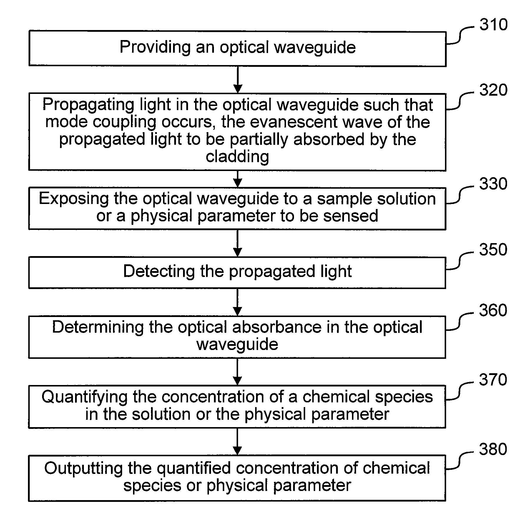
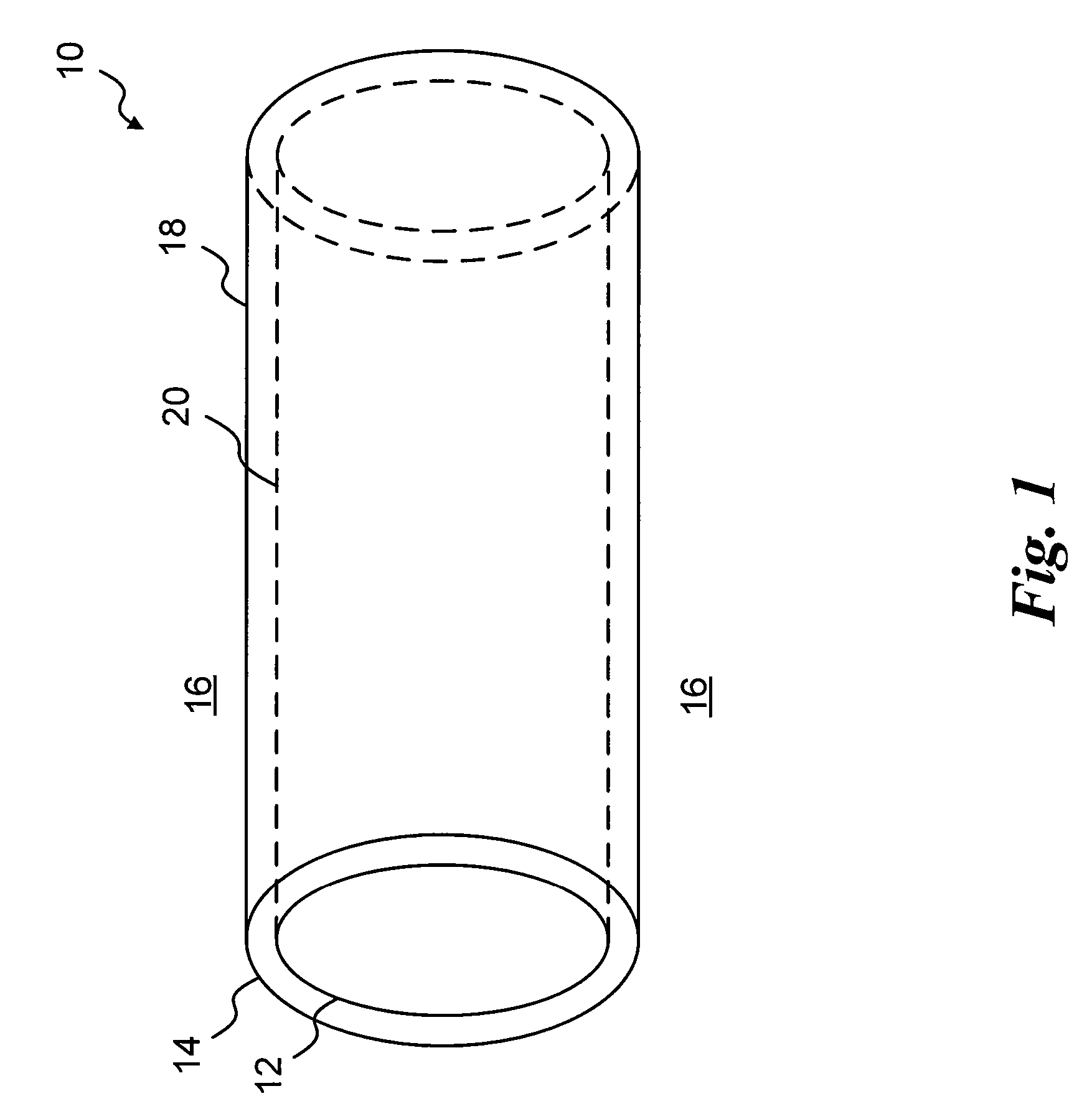
[0017]There is provided an evanescent wave multimode optical waveguide sensitive to a chemical species or to a physical parameter. The optical waveguide comprises an optical waveguide core having a core refractive index and a cladding surrounding the core and having a cladding refractive index lower than the core refractive index for guiding light to be propagated in the optical waveguide such that an evanescent wave of light propagates in the cladding. The cladding defines with the core an optical waveguide providing mode coupling such that multiple modes of the propagated light are coupled while light propagates along the optical waveguide. A chemical indicator is provided in the cladding. The indicator causing a variation of the optical absorption of the cladding as a function of the chemical species or the physical parameter. The evanescent wave propagating in the cladding resulting in light to be at least partly absorbed by the indicator. The mode coupling causing unabsorbed light power to be redistributed among the multiple modes while light propagates along the optical waveguide.

Problems solved by technology

Reliable quantification of the concentration of the absorbing species is therefore not straightforward.

Method used


Image

  • Evanescent wave multimode optical waveguide and sensor with high mode coupling
  • Evanescent wave multimode optical waveguide and sensor with high mode coupling
  • Evanescent wave multimode optical waveguide and sensor with high mode coupling

Examples


example 1

RING BY PREFORM DRAWING

[0060]In one embodiment, the core of the preform is made from a commercial rod of Plexiglas® having a diameter of 11 mm with a refractive index n20D of 1.491 and a glass transition temperature Tg of about 108-109° C. The preform is prepared by multiple constant-speed immersions of the Plexiglas® rod into a solution of the selected cladding material compound until the desired layer thickness is reached on the perform. In this case, the cladding matrix is made of a copolymer poly(methyl methacrylate-co-decyl methacrylate) (pMMA-DMA) (n20D=1.476) synthesized in benzene. The pMMA-DMA-based cladding cocktail also comprises chromoionophore ETH 5294, anionic sites tetrakis[3,5-bis(trifluoromethyl)phenyl]borate sodium (NaTFPB), and potassium-selective ionophore valinomycin using tetrahydrofuran as the solvent. Fiber drawing is performed at a furnace temperature of 200° C. In those conditions, preform temperature does not exceed 180° C. but maintains this temperature f...

example 2

[0061]FIG. 3 shows experimental optical absorption spectra illustrating the sensitivity of an optical fiber having a Ca2+-selective nBA-MMA cladding painted on a bare PMMA fiber core. The different curves show the optical spectra of the fiber obtained when immersed in solutions of various concentrations of CaCl2. The spectra are baseline-corrected and normalized to the isobestic wavelength of 571 μm. FIG. 4 shows the calibration curve of the Ca2+-selective optical fiber and FIG. 5 shows the time response of the Ca2+ selective optical fiber.

[0062]The Ca2+-selective optical fiber under test is made from a Plexiglas® fiber core drawn, using drawing techniques known in the art, from a 10 cm Plexiglas® (PMMA) rod having a 10 mm diameter. A 400 μm optical fiber core is obtained. A 10 cm-long section of optical fiber core is then coated by painting a solution of the polymeric cladding mixture dissolved in tetrahydrofuran to provide the sensing cladding. A dried coating of approximately 4 μ...


PUM

PropertyMeasurementUnit
mode coupling lengthaaaaaaaaaa
refractive indicesaaaaaaaaaa
refractive indexaaaaaaaaaa

Abstract

There is provided an evanescent wave multimode optical waveguide sensitive to a chemical species or to a physical parameter. The optical waveguide comprises a core and a cladding having a cladding refractive index lower than that of the core for guiding light to be propagated in the optical waveguide. The cladding defines with the core an optical waveguide providing mode coupling. A chemical indicator is provided in the cladding for causing a variation of the optical absorption of the cladding as a function of the chemical species or the physical parameter. The cladding is interrogated by the evanescent wave of the propagated light. The mode coupling causes unabsorbed light power to be redistributed among the multiple modes while light propagates along the optical waveguide.

Description

BACKGROUND OF THE INVENTION[0001]1. Field of the Invention[0002]The present invention relates to evanescent wave optical waveguide sensors for measuring chemical or physical parameters. More particularly, the present invention relates to chemical sensors and more specifically to ion-selective sensors.[0003]2. Background Art[0004]Chemical sensors are used in various applications including environmental emission control, agri-food industry, and other industrial applications. They are also used in biomedical applications and clinical analysis for determining the pH, the presence of specific ions or the oxygen or alcohol concentration in a sample solution for example. Optical chemical analysis methods include, for example, Fourier transform infrared spectroscopy.[0005]Optical fiber based optodes generally use a sensing membrane deposited at the fiber tip which was previously cleaved and polished. Alternatively, evanescent wave spectroscopy uses an optical waveguide that is immersed into...

Claims


Application Information

Patent Timeline
Patent Type & Authority Applications(United States)
IPC IPC(8): G01N21/00G02B6/00
CPCG01N21/7703G01N2021/7716G01N2021/7759
Inventor CARON, SERGEMOUSLINKINA, LIAPARE, CLAUDEFOUGERES, ANDRE
Owner INSTITUT NATIONAL D'OPTIQUE
Why Eureka
Try Eureka