
Proton exchange membrane fuel cell

a technology of protons and fuel cells, applied in the direction of fuel cells, solid electrolyte fuel cells, cell components, etc., can solve the problems of reducing ph, and affecting the efficiency of fuel cell stacks

Active Publication Date: 2008-12-11
EMERGENT POWER
View PDF38 Cites 8 Cited by
  • Summary
  • Abstract
  • Description
  • Claims
  • Application Information

AI Technical Summary

Benefits of technology

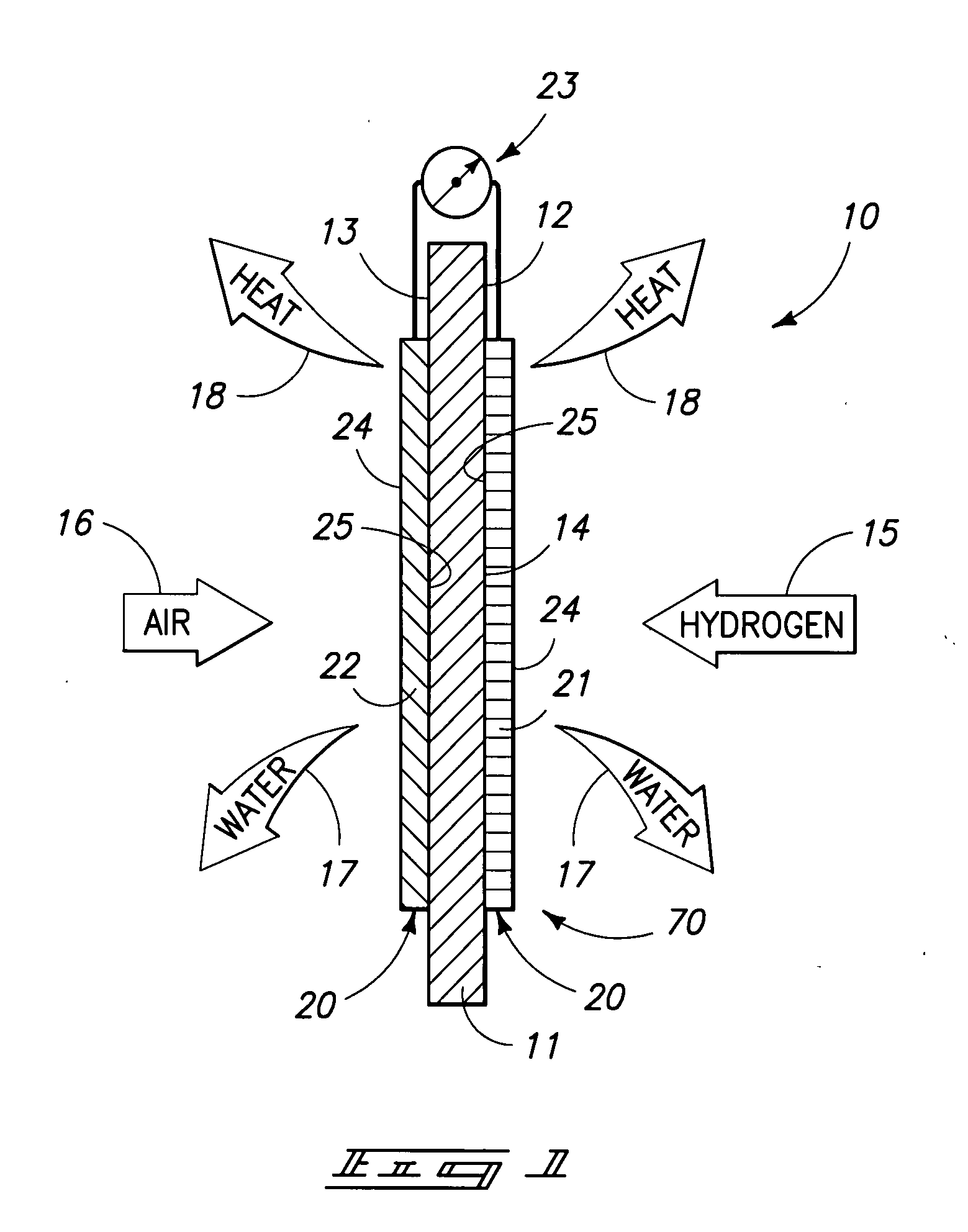
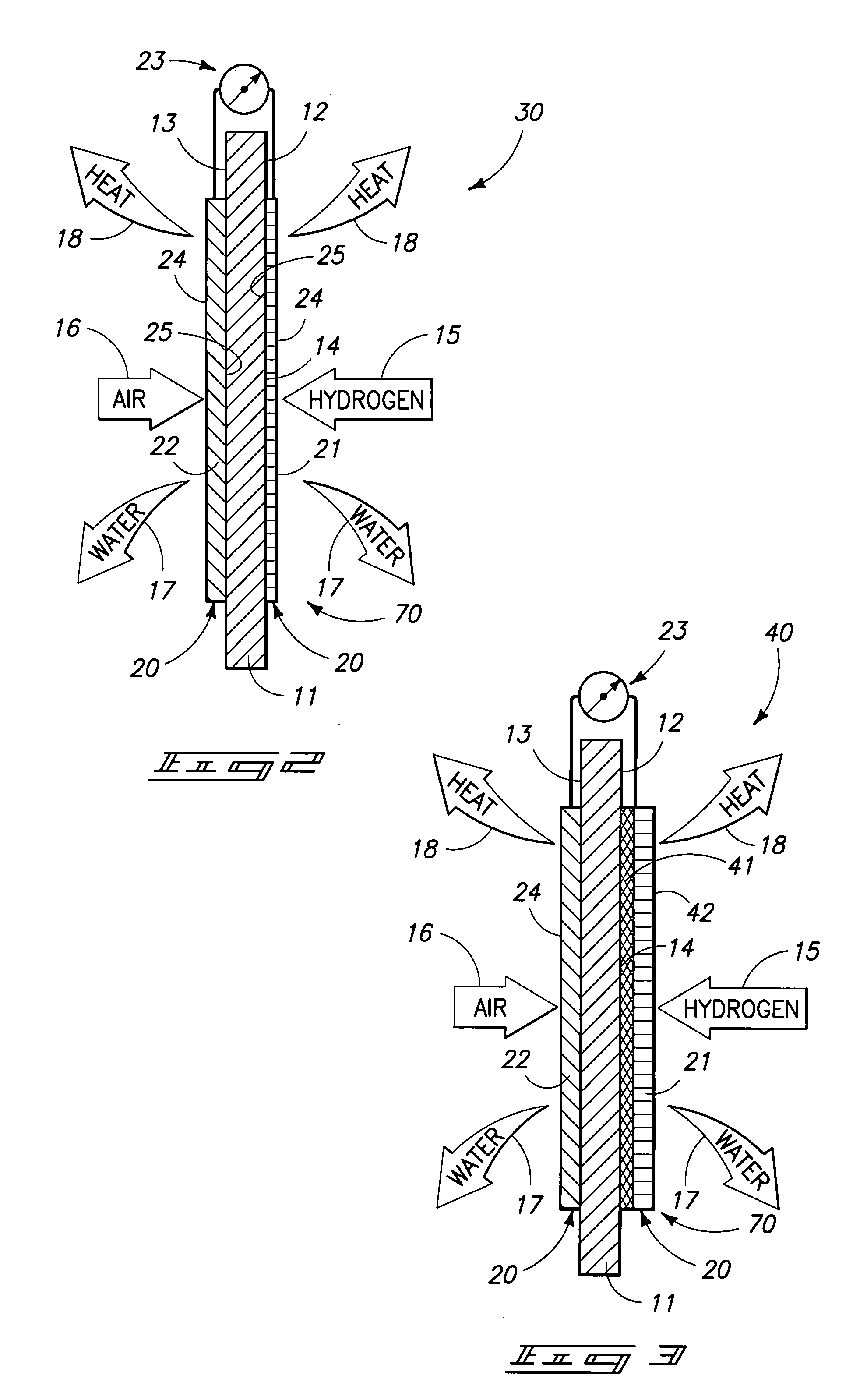
[0016]Still another aspect of the present invention relates to a proton exchange membrane fuel cell which includes a proton exchange membrane having opposite anode and cathode sides; and a pair of porous, electrically and thermally conductive ceramic gas diffusion layers individually juxtaposed relative to the anode and cathode sides respectively, and wherein the respective ceramic gas diffusion layers retain an operatively effective amount of liquid water which is generated as a byproduct of the operation of the proton exchange membrane fuel cell so as to render the proton exchange membrane fuel cell substantially self-humidifying.

Problems solved by technology

Those skilled in the art have long recognized that fuel cell stacks have limitations inherent in their design.
If Nation® is immersed in water, the water becomes somewhat acidic.
In this situation, the Nation® absorbs the hydroxyl groups and leaves excessive hydrogen ions in the water causing the pH to decrease.
Additionally, the management of the heat energy generated by prior art fuel cells have presented unique challenges for fuel cell designers.
The excessive evaporation initiates a hydration spiral which causes the eventual shutdown (and even irreparable damage) of the proton exchange membrane.
Therefore, the design of a fuel cell which addresses the myriad of problems of adequate hydration and management of heat during operation of the fuel cell has been uniquely challenging and difficult for one skilled in the art because prior art fuel cells are often deployed in environments where the ambient temperatures and humidities often widely vary over 24-hour time periods.
However, in these fuel cell devices, water cannot, nor need not, be retained by the ceramic hydrophilic gas diffusion layers employed with same in view of the high operating temperatures (600-900°).
Rather, the high temperature of operation of SOFC devices renders the electrolyte ionically conductive.
As should be gathered from the discussion above, the cost of fabricating such SOFC devices have been significant.
Further, to render such devices operational, rather complex and sophisticated balance of plant arrangements, and control systems must be employed to controllably heat the SOFC device up to an operational temperature, and then maintain the device within acceptable temperature ranges so as to maintain the ceramic electrolyte ionically conductive.
While traditional proton exchange membrane fuel cell stacks and modules of various designs have operated with some degree of success, a number of shortcomings continue to detract from their usefulness, and have presented quite unique and difficult engineering challenges for prior art fuel cell designers.
First among these shortcomings is the relatively high cost of manufacture for the individual components of a traditional proton exchange membrane fuel cell stack.
Still further, another problem attendant with the operation of various fuel cell stack designs includes those associated with the management of the proper hydration, and cooling of the fuel cell stack.
However, too much water tends to “flood out” the cell, thereby impairing or stopping the operation of the fuel cell.
Still further, while some heat is necessary to achieve an acceptable electrical output, too much heat can cause excessive dehydration which may cause the fuel cell to enter into a hydration spiral where the proton exchange membrane may become breached or otherwise fail to operate effectively.
Further, “hot spots” may develop, and these hot spots have the effect of degrading the electrical output of the proton exchange membrane fuel cell stack.
As should be understood, a number of sophisticated technologies and designs have been developed to manage these hot spots, but the result has been higher manufacturing costs and greater complexity for the resulting fuel cell stack system.
However, this has only increased the cost of the resulting fuel cells.
More specifically, the cost per watt of generated electrical power has far exceeded the cost of electricity taken from most electrical grids.
Notwithstanding these efforts, the prior art fuel cells have not been widely embraced except in narrow market segments where the costs of manufacture are usually not as important as having a product that can generate electricity for that particular application.

Method used


Image

  • Proton exchange membrane fuel cell
  • Proton exchange membrane fuel cell
  • Proton exchange membrane fuel cell

Examples


example 1

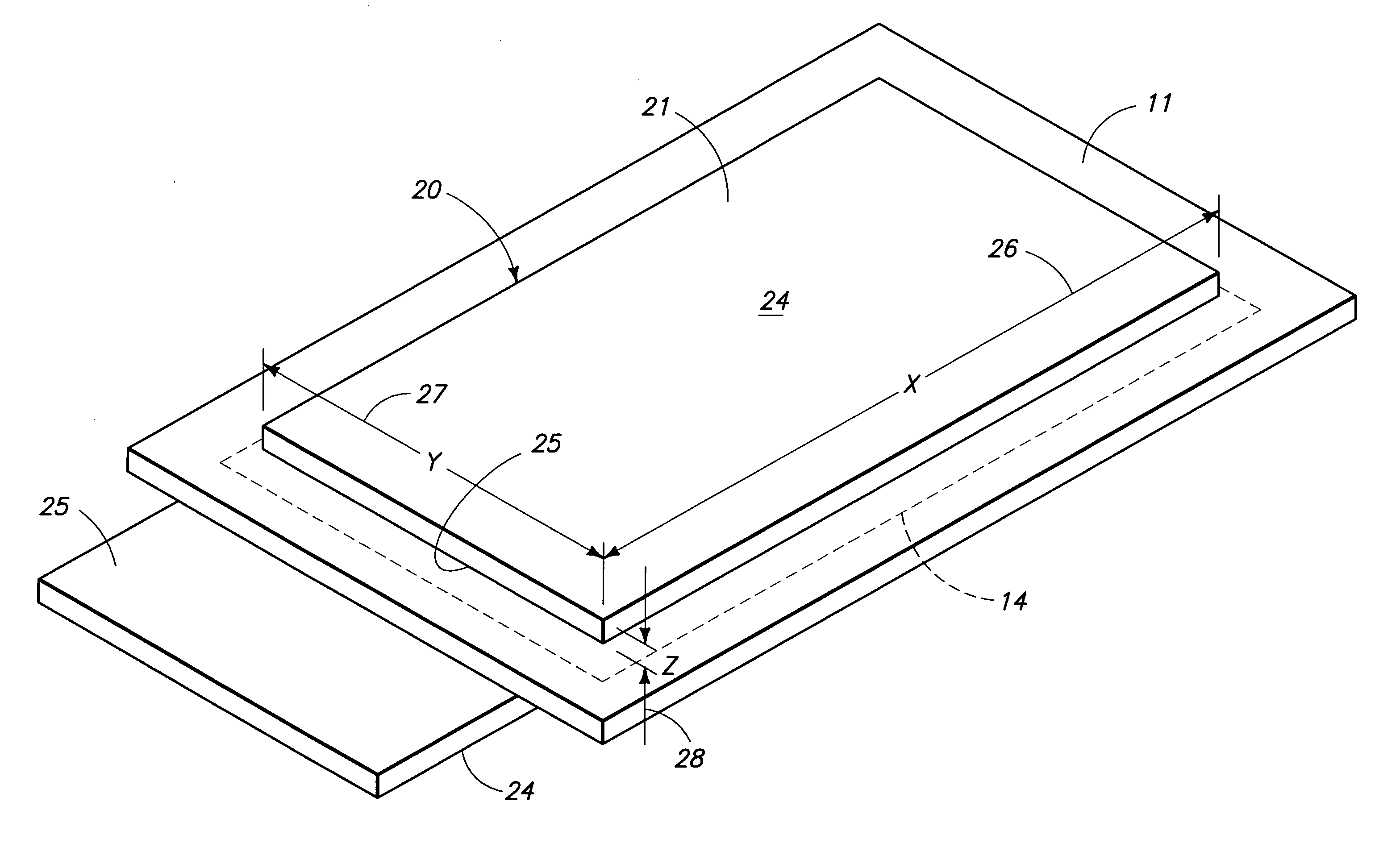
[0042]A PEM fuel cell utilizing molybdenum disilicide as the porous, electrically conductive anode and cathode diffusion layers was examined. A test cell was assembled using a 16 square centimeter test fixture developed by the inventors. The cell was assembled using a proton exchange membrane-electrode assembly commercially available from W.L. Gore, and which was sized to fit the text fixture. The molybdenum disilicide gas diffusion layers were fabricated to be slightly undersized, that is, each had a surface area of approximately 11.5 square centimeters. Aluminum foam pieces were used as heat sinks on the anode and cathode sides of the fuel cell, with the cathode heat sink also functioning as a current collector. The molybdenum disilicide gas diffusion layers each had a measured permeability of approximately 1800 Gurley-seconds for the anode gas diffusion layer; and approximately 900 Gurley-seconds for the cathode gas diffusion layer. A nonwoven, carbon-based micro-gas diffusion la...

example 2

[0043]A PEM fuel cell utilizing titanium disilicide as the porous, electrically conductive anode and cathode diffusion layers was examined. A test cell was assembled using a 16 square centimeter test fixture developed the inventors. The cell was assembled using a proton exchange membrane-electrode assembly commercially available from W.L. Gore and which was sized to fit the text fixture. Titanium disilicide was used to fabricate both the anode and cathode gas diffusion layers. Silver-plated folded fin copper was used to fabricate heat sinks which rested in heat transferring relation relative to both the anode and cathode sides of the fuel cell. The cathode titanium disilicide gas diffusion layer had a measured permeability of approximately 170 Gurley-seconds. The anode titanium disilicide gas diffusion layer had a slightly higher permeability, which was measured at approximately 110 Gurley-seconds. A nonwoven, carbon-based micro-gas diffusion layer, commercially available from Freud...

example 3

[0044]A PEM fuel cell utilizing titanium nitride as the porous, electrically conductive cathode diffusion layer and titanium diboride as the porous, electrically conductive anode diffusion layer was examined. A test cell was assembled using a 16 square centimeter test fixture developed by the inventors. The fuel cell was assembled using a commercially available proton exchange membrane-electrode assembly which was secured from W.L. Gore. It was sized to fit the text fixture. The titanium nitride and titanium diboride gas diffusion layers were fabricated to be slightly undersized, that is, each with a surface area of approximately 11.5 square centimeters. Aluminum foam pieces were used as heat sinks on the anode and cathode sides of the fuel cell. The cathode heat sink also functioned as a current collector. The titanium nitride cathode gas diffusion layer had a measured permeability of approximately 730 Gurley-seconds. A nonwoven, carbon-based micro-gas diffusion layer, which is com...


PUM

PropertyMeasurementUnit
pore sizeaaaaaaaaaa
voltageaaaaaaaaaa
voltageaaaaaaaaaa

Abstract

A proton exchange membrane fuel cell is described and which includes a proton exchange membrane having at least one gas diffusion layer which is juxtaposed relative thereto, and which is fabricated, at least in part, of a porous, electrically conductive, inorganic material which is selected from the group comprising metal diborides, metal disilicides, metal nitrides, metal carbides, and composites, laminates and solid solutions thereof.

Description

TECHNICAL FIELD[0001]The present invention relates to proton exchange membrane fuel cell which includes at least one porous electrically conductive inorganic gas diffusion layer.BACKGROUND OF THE INVENTION[0002]A fuel cell is an electrochemical device which reacts hydrogen, as a fuel source, and oxygen, which is usually derived from ambient air, to produce electricity, water and heat. The basic process is highly efficient in fuel cells fueled by pure hydrogen, and it is substantially pollution free. Further, since fuel cells can be assembled into various arrangements, power systems have been developed to produce a wide range of electrical power outputs. As a result of these attributes, fuel cell power systems hold a great deal of promise as an environmentally friendly and valuable source of electricity for a great number of applications.[0003]One of a number of known fuel cell technologies is the proton exchange membrane (PEM) fuel cell. The fundamental electrochemical process under...

Claims


Application Information

Patent Timeline
Patent Type & Authority Applications(United States)
IPC IPC(8): H01M8/10
CPCH01M4/8807H01M8/0236H01M8/0245H01M8/1004Y02E60/521Y02E60/50
Inventor SPINK, SCOTT A.LOTT, DAVID R.WRIGHT, MATTHEW M.YEMUL, DINESH S.FUGLEVAND, WILLIAM A.BAYYUK, SHIBLIHANNA I.DUAN, RUNRUNBAI, LIJUN
Owner EMERGENT POWER
Learn More