
Optical member, optical system using the optical member, and method of manufacturing an optical member

a technology of optical components and optical components, applied in the field of optical components, can solve the problems of reduced performance, alkali ions, elution of substrate components, etc., and achieve the effects of excellent optical characteristics, easy production, and high productivity

Active Publication Date: 2008-12-18
CANON KK
View PDF11 Cites 82 Cited by
  • Summary
  • Abstract
  • Description
  • Claims
  • Application Information

AI Technical Summary

Benefits of technology

[0009]A metal oxide and a metal halide layer to be formed by a technology using fine particles or a method of growing boehmite on a substrate is produced easily with a high productivity and exhibits excellent optical characteristics. On the other hand, such a metal oxide and a metal halide layer have a low density and a number of voids, so moisture or the like reaches the substrate easily from outside, which easily causes the erosion of the substrate and the elution of a substrate component such as alkali ions. Further, there is a problem in that the eluted component makes it difficult to keep the fine structure, resulting in decreased performance.
[0011]There is a demand for an antireflection film using a fine periodic structure, which can be formed more easily and has high reliability in low-temperature sintering.
[0012]The present invention has been made in view of the related art described above, and an object is to provide an optical member which can maintain a high-performance antireflection effect over a long period of time for any substrate, an optical system using the same and a method of manufacturing an optical member.
[0026]According to the present invention, an optical member capable of exhibiting a high antireflection effect stably over a long period of time can be provided.

Problems solved by technology

On the other hand, such a metal oxide and a metal halide layer have a low density and a number of voids, so moisture or the like reaches the substrate easily from outside, which easily causes the erosion of the substrate and the elution of a substrate component such as alkali ions.
Further, there is a problem in that the eluted component makes it difficult to keep the fine structure, resulting in decreased performance.

Method used


Image

  • Optical member, optical system using the optical member, and method of manufacturing an optical member
  • Optical member, optical system using the optical member, and method of manufacturing an optical member
  • Optical member, optical system using the optical member, and method of manufacturing an optical member

Examples


example 1

[0140]An appropriate amount of the polyimide solution 6 was dropped onto one surface of the S-TIH53 (n550nm=1.84) substrate washed by the above method, followed by spin coating at 3,000 rpm for 20 seconds. The substrate was pre-dried at 80° C. for 10 minutes, and thereafter, the other surface was similarly spin-coated with the polyimide solution 6. After that, the resultant substrate was sintered in a hot air circulation oven at 200° C. for 30 minutes, whereby a substrate with an organic resin layer having the polyimide 1 on both surfaces was produced. Table 2 shows the thickness, refractive index, and percentage of water absorption of the polyimide film 1.

[0141]An appropriate amount of an alumina sol solution 14 was dropped onto one surface of the substrate with the film of the polyimide 1, followed by spin coating at 4,000 rpm for 20 seconds and pre-drying at 80° C. for 10 minutes. The other surface was similarly spin coated with the alumina sol solution. After that, the resultant...

example 2

[0146]The same operation as in Example 1 was conducted except for using the polyimide solution 7 in place of the polyimide solution 6 to form an organic resin layer formed of the polyimide 2.

example 3

[0147]The same operation as in Example 2 was conducted except for replacing the substrate by S-LAH65 (n550nm=1.80).


PUM


Abstract

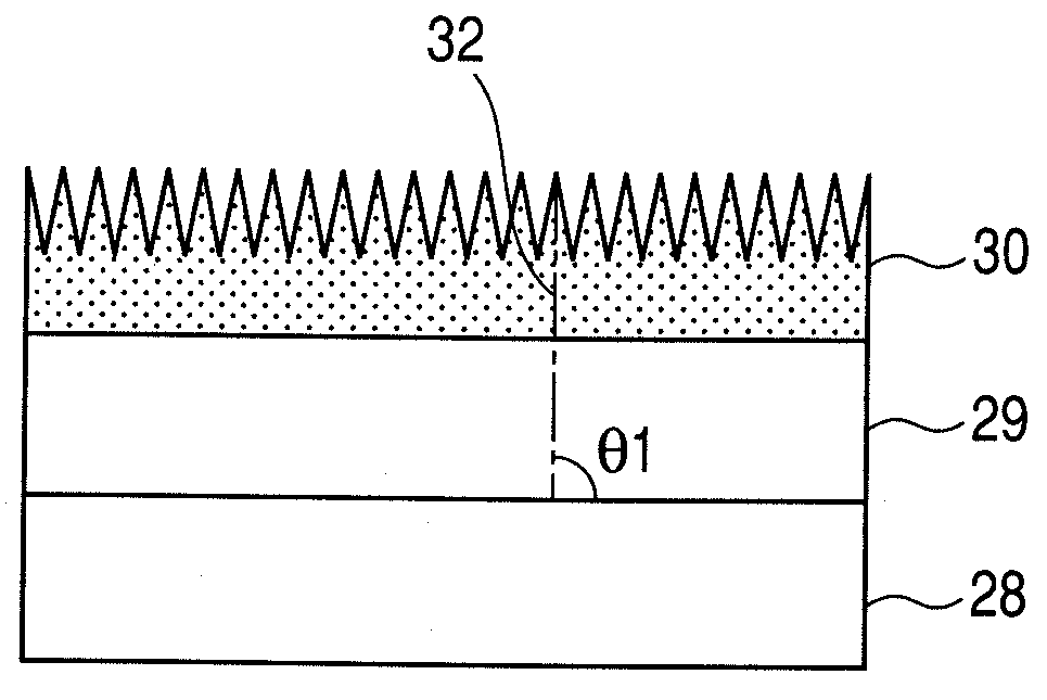
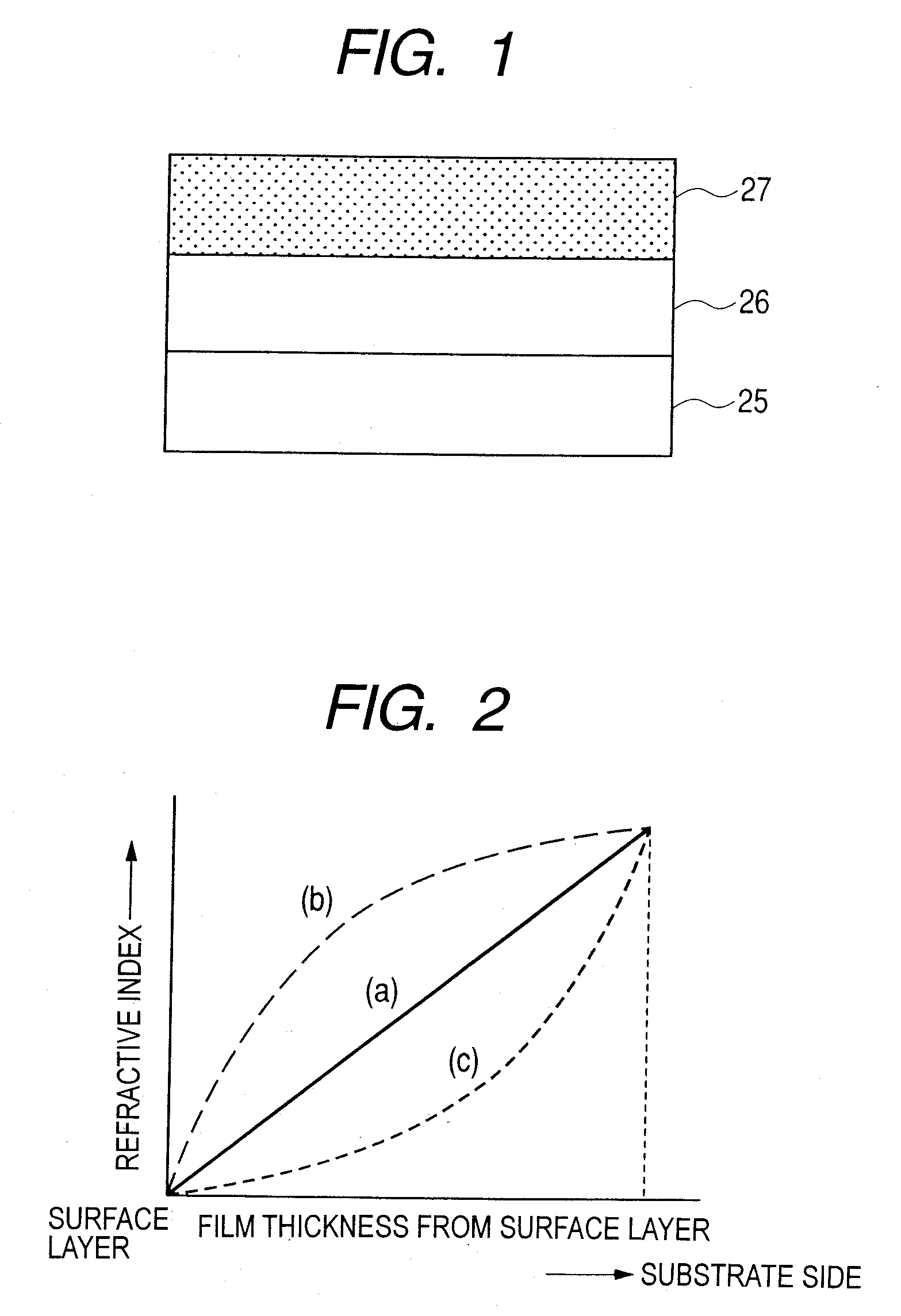
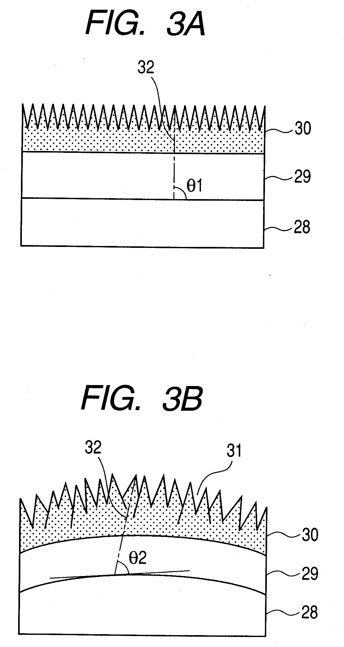
Provides is an optical member capable of keeping a high performance antireflection effect over a long period of time with respect to an arbitrary substrate. The optical member has plural layers on a substrate, and includes at least one metal oxide layer having a void, and at least one layer containing an organic resin as a main component formed between the substrate and the metal oxide layer. The metal oxide layer is a plate crystal layer formed of a plate crystal containing aluminum oxide as a main component and a surface of the plate crystal layer has an uneven profile. The organic resin has an aromatic ring and / or a hetero ring in at least a part thereof.

Description

CROSS-REFERENCE TO RELATED APPLICATIONS[0001]This application is a continuation of International Application No. PCT / JP2008 / 053129, filed Feb. 19, 2008, which claims the benefit of Japanese Patent Applications No. 2007-040003, filed Feb. 20, 2007, and No. 2008-033290, filed Feb. 14, 2008.BACKGROUND OF THE INVENTION[0002]1. Field of the Invention[0003]The present invention relates to an optical member having an antireflection property and an optical system using the same, and more particularly, to an optical member suitable for obtaining a high antireflection property in a visible region to a near infrared region over a long period of time, and an optical system using the same.[0004]2. Description of the Related Art[0005]It is known that an antireflection structure using a fine periodic structure having a wavelength of the visible light region or a shorter wavelength forms a fine periodic structure having an appropriate pitch and height, and thereby shows an excellent antireflection ...

Claims


Application Information

Patent Timeline
IPC IPC(8): G02B1/11G02B1/02B32B13/04B05D5/06G02B1/10B32B9/00G02B1/118
CPCG02B1/118C03C1/006C03C2217/425C03C2217/73C03C2217/465C09D179/08G02B1/02Y10T428/24942Y10T428/269Y10T428/24612C03C17/42C03C2217/77Y10T428/265G02B1/111Y10T428/31504Y10T428/31616Y10T428/31623Y10T428/31663Y10T428/31667Y10T428/31681Y10T428/31721C09D171/00
Inventor NAKAYAMA, TOMONARIYAMADA, MASAYUKI
Owner CANON KK
Learn More