Method and System for Low Radiation Computed Tomography

a computed tomography and low radiation technology, applied in tomography, instruments, applications, etc., can solve the problems of reducing contrast, affecting diagnostic accuracy, and lesions that are more difficult to detect, so as to reduce the effect of beam hardening and improving soft tissue differentiation

Active Publication Date: 2008-12-25
SOCPRA SCI SANTE & HUMAINES S E C
View PDF5 Cites 51 Cited by
  • Summary
  • Abstract
  • Description
  • Claims
  • Application Information

AI Technical Summary

Benefits of technology

[0032]Further improvement can be accomplished by approximating the weight of individual detected events proportionally to E−3, which is close to the variation of attenuation cross section for photons in the radiologic energy range (10-100 keV). The inclusion of energy (or spectral) data in the image provides an additional means of improving soft tissue differentiation by reducing the effects of beam hardening and permits some degree of correction for scattered X-rays in the image. Moreover, the system allows providing higher contrast images for the same dose, or similar contrast images for a lower dose to the subject compare to CT system according to the prior art.

Problems solved by technology

This issue is particularly preoccupying in pediatric scanning, as the human body is still growing and more prone to developing cancer 10 or 20 years later as a result of dose exposure.
However, reducing the radiation dose on CT procedures has the effect to increase image noise, thus reducing contrast, making lesions more difficult to detect and ultimately affecting diagnostic accuracy.
Significant short-term stimulation effects (DNA repair mechanisms, immune response, free-radical detoxification and apoptosis) and long-term effects of radiation-induced damage have been reported in this dose range, which may potentially have confounding biological effects biasing research results.
In another respect, the inherent integration of the X-ray beam energy has the detrimental consequence of exacerbating the so-called beam hardening effect, by increasing the weight of high energy X-rays relative to low energy X-rays proportionally to the X-ray photon energy.
Another adverse consequence of X-ray integrating systems, which imposes strict stability requirements on the entire systems, is that the noise from all sources (electronic, variance due to scintillation photon or charge carrier statistics, afterglow in phosphors, systematic signal bias) is integrated and measured together with the signal in acquiring CT data, leading to noisier projection data and degraded image contrast.
Another related consequence is that more powerful, cumbersome and expensive X-ray tubes with complex cooling systems must be used to reduce imaging times.
It has been found that such a system is severely statistics limited for high-rate photon counting CT.
The use of an individual readout channel per detector pixel was also found to be count rate limited due to the long charge collection time which increases dead time and severely limits the maximum event rate that can be processed [3].
Semiconductor detectors also suffer from low detection efficiency in the higher diagnostic energy range.
Even though thicker semiconductor diodes has been proposed to overcome this problem, their use increases the cost of the detector and the charge migration time adds extra dead time that further limits the detector count rate.
However, such systems require detector cooling, typically to 77° K, and they must be used in conjunction with low-noise charge preamplifiers having a long integration time to collect the slow drifting charge carriers from the bulk of the detector material.
Moreover, such systems are generally much too expensive to be considered for a large-scale application, such as medical imaging scanners.
A drawback of this method is that it requires ultra-low noise detectors and extremely fast readout rates to achieve the detector count rate required for use in CT imaging.

Method used


Image

  • Method and System for Low Radiation Computed Tomography
  • Method and System for Low Radiation Computed Tomography
  • Method and System for Low Radiation Computed Tomography

Examples


Embodiment Construction

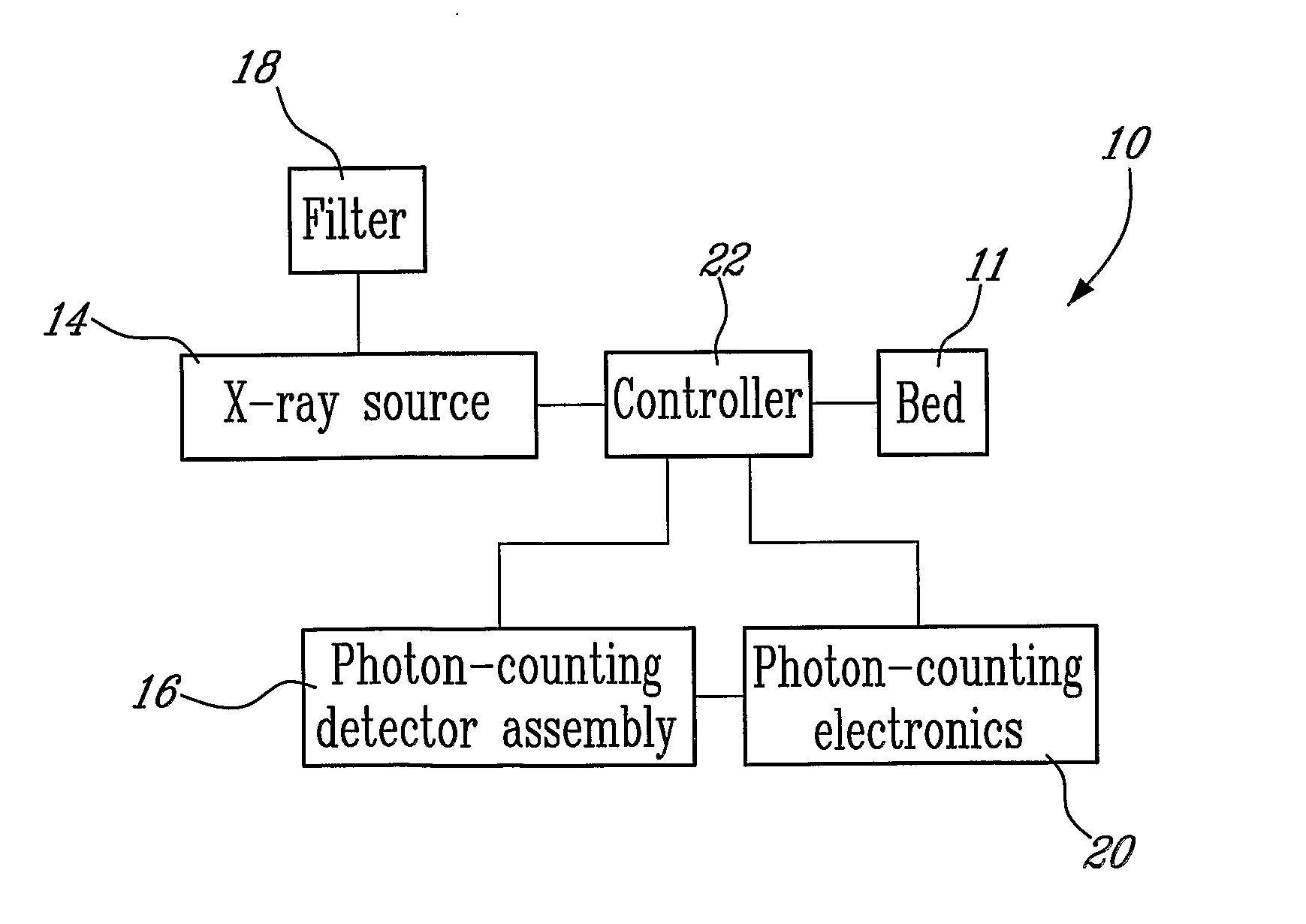
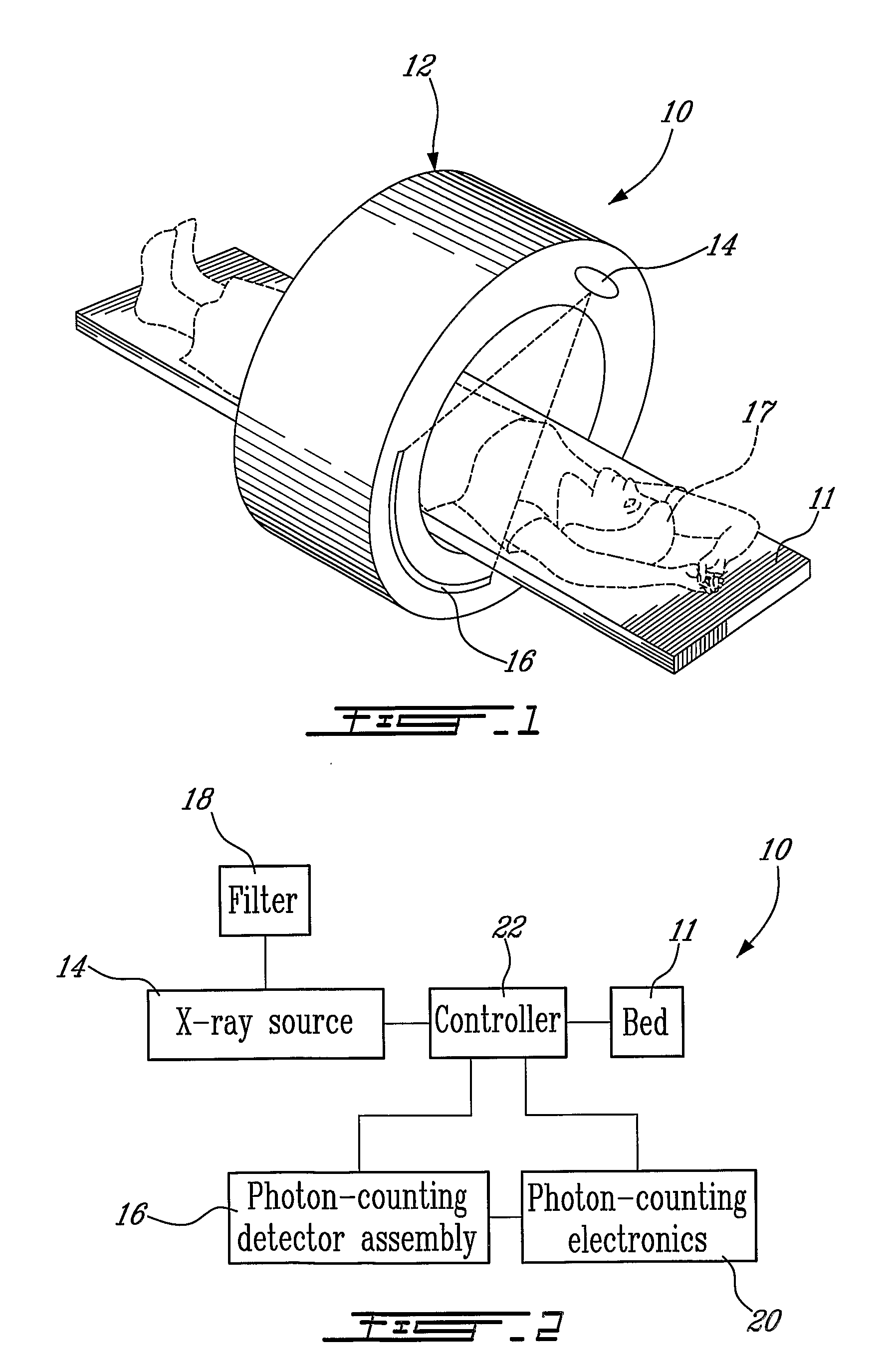
[0042]A system 10 for low radiation computed tomography according to an illustrative embodiment of the present invention will now be described with reference to FIGS. 1-2.

[0043]The system 10 comprises a subject-receiving area in the form of a bed 11 and an enclosure 12 partially surrounding the bed 11 containing a low energy radiation source, in the form of an X-ray source 14, and a detector assembly 16.

[0044]The enclosure 12 is generally in the form of a cylinder positioned about the bed 11 defining a tunnel therein. The X-ray source 14, is for example an X-ray tube mounted in the enclosure 12 so as to project a low energy radiation beam towards the radiation detector array 16 after passage through the patient 17.

[0045]The X-ray tube 14 may be for example of the microfocus or microfocus rod X-ray tube type.

[0046]Other types of X-ray sources including without limitations rotating targets and dual spots can also be used.

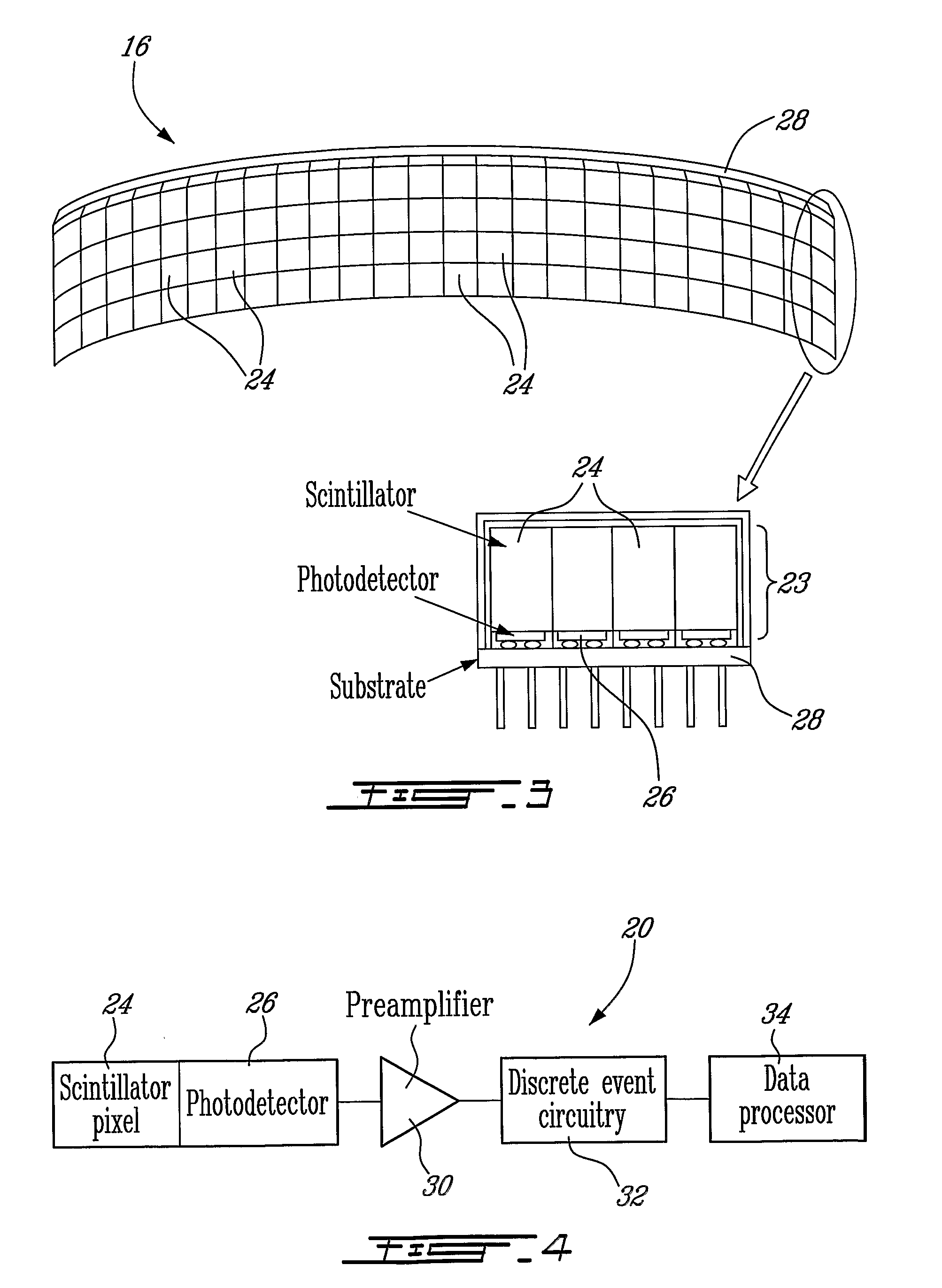
[0047]The detector assembly 16 is located in the enclosure oppos...


PUM


Abstract

A method for single photon counting transmission computed tomography (CT) is described. The method is based on an apparatus consisting of a radiation source and detectors on an opposite side of the subject from the source. The radiation source is for example an X-ray tube. The detectors are independently connected to parallel, fast, low-noise processing electronics capable of recording and counting individual X-ray photons at very high rate. In one embodiment of the invention, said detector is made of a scintillator coupled to a photodetector. The photodetector can be an avalanche photodiode (APD). The method comprises the steps of: directing the low energy radiation source toward the subject; detecting the radiation transmitted through the subject towards the detectors and recording the position and energy of each individual X-ray photon; rotating the radiation source and detectors around the subject; recording data for each position of the radiation source and detectors around the subject to form projections; and creating a CT image from the recorded projection data. The proposed method allows enhancing CT image contrast and reducing radiation dose to the patient by counting individual X-ray photons.

Description

FIELD OF THE INVENTION[0001]The present invention relates to transmission computed tomography (CT). More specifically, the present invention is concerned with a method and system for low radiation computed tomographyBACKGROUND OF THE INVENTION[0002]Computed tomography (CT) is a well-known method for obtaining images of the internal structure of a subject from its projections. In X-ray CT, these projections are obtained by rotating an external radiation source, usually an X-ray tube, around the subject and measuring the X-ray transmission through the field of view with an opposite X-ray detector array. The measured intensity of the transmitted X-ray flux through the subject, in reference to the measured intensity without the subject, provides a measure of the mean attenuation through the body tissues, which in turn provides information on the tissue density and composition. A set of projections, obtained over 180° or 360°, is then processed by a tomographic reconstruction algorithm w...

Claims


Application Information

Patent Timeline
Patent Type & Authority Applications(United States)
IPC IPC(8): A61B6/00
CPCA61B6/032A61B6/482G01T1/2985A61B6/508
Inventor LECOMTE, ROGERBERARD, PHILIPPECADORETTE, JULESLAPOINTE, DAVID
Owner SOCPRA SCI SANTE & HUMAINES S E C
Why Eureka
Try Eureka