Millimeter wave imager with visible or infrared overlay for brownout assist

Inactive Publication Date: 2009-01-01
TREX ENTERPRISES CORP
View PDF11 Cites 53 Cited by
  • Summary
  • Abstract
  • Description
  • Claims
  • Application Information

AI Technical Summary

Benefits of technology

[0015]A pilot's eyes, and imaging systems of equivalent resolution in the visible and infrared portions of the electromagnetic spectrum, are able to select a suitable landing zone well in advance of the onset of brownout conditions, which are caused by rotor downdraft only during the final descent stage of the helicopter. This application teaches a means for overlaying a static high-resolution image, taken prior to brownout with a visible light (CCD or CMOS-based) sensor or infrared (short-wave, mid-wave, or long-wave) camera with a dynamic MMW radar image to provide the contextual benefits of the high-resolution imagery along with the penetrating ability of the MMW radar.
[0016]An image from a high-resolution video or infrared camera is captured as the helicopter nears a chosen landing site, and is registered in real time against a 3-dimensional MMW radar image, using a multi-modal image registration algorithm based upon localized wavelet transforms. By its nature, this type of registration algorithm allows for slight warping of one image relative to the other, in scale factor, translation, tip, tilt and rotation. The resulting correlation matrix describing the scene registration is then repeatedly updated using the dynamic MMW radar imagery against the captured, static high-resolution image. The static image is continuously remapped onto a suitable ground projection based upon the original high-resolution data and the scale, translation, tip, tilt and rotation factors from the updated correlation matrix, and the resulting (high-resolution) projection is presented to the pilot along with the radar range data on a display monitor. The pilot lands the aircraft based upon height information from the radar and projection information from the static image. As the helicopter height above ground level decreases, the radar footprint also decreases, improving the resolution of the radar projection and along with it the quality of the dynamic/static scene registration. Protrusions from the landing surface, as detected by the radar, are displayed with a shaded gray-scale or artificial color scheme to present a suitable 3-dimensional image for landing assist.
[0017]While MMW radar provides sufficient penetration and resolution to enable safe helicopter landing at a specified location, the beamwidth of MMW radar (typically a few tenths of a degree, up to one degree) cannot resolve ground features with sufficient resolution to allow preferential landing zone selecti

Problems solved by technology

Passive imaging demands the ultimate state-of-the-art in receiver noise performance, resulting in high cost solutions, and further requires at least two distinct imaging apertures in order to establish ranging, an essential component of safe landing information.
For landing applications, radar power requirements are very small, so the only downside to using active radar rather than passive radiometry is an increased probability of detection.
Lower frequencies cannot provide sufficient spatial resolution from a practical antenna aperture; higher frequencies suffer from incre

Method used


Image

  • Millimeter wave imager with visible or infrared overlay for brownout assist
  • Millimeter wave imager with visible or infrared overlay for brownout assist
  • Millimeter wave imager with visible or infrared overlay for brownout assist

Examples


Example

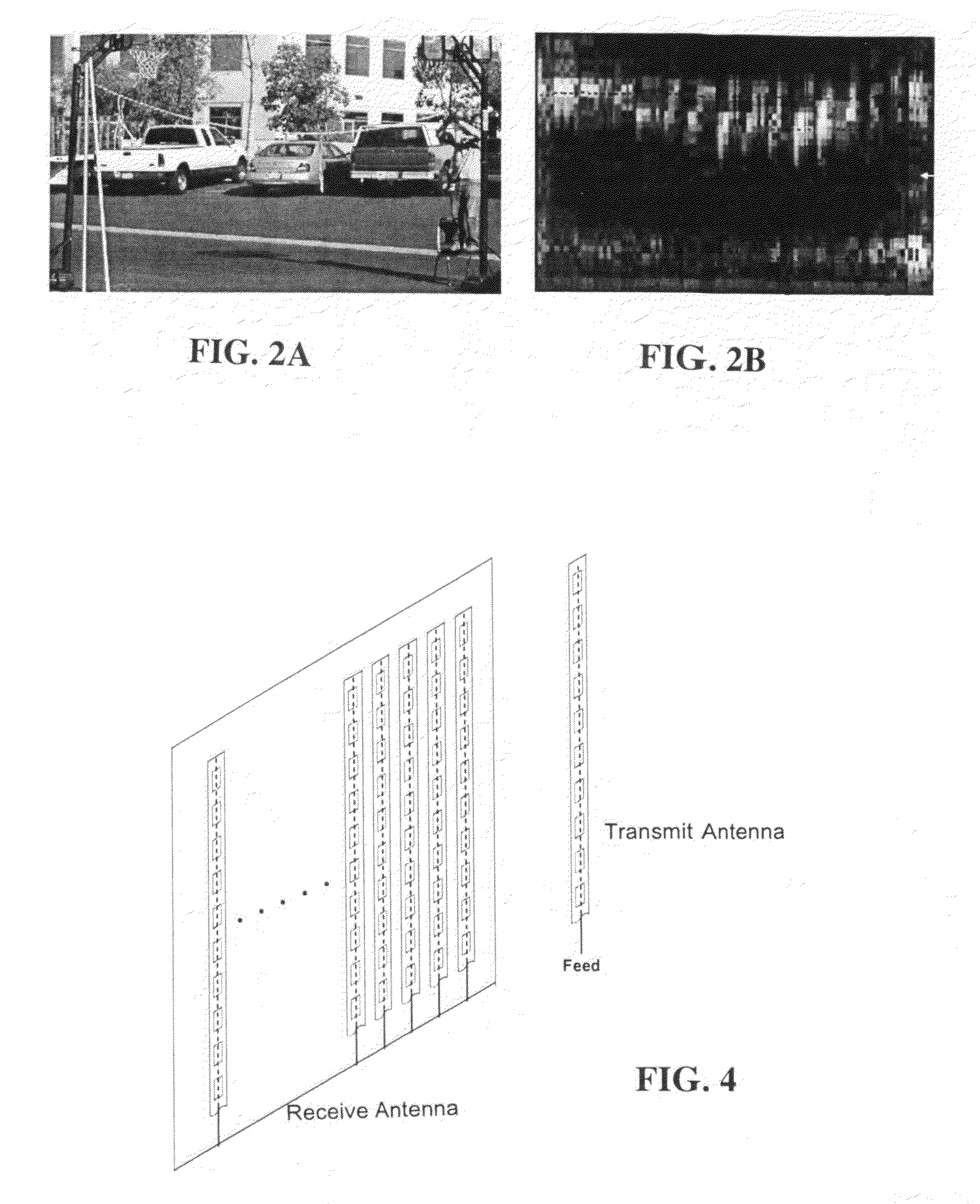
[0029]A first preferred embodiment of the present invention, sometimes herein referred to as the “Sandblaster Imaging Radar” or the “Sandblaster” comprises an FMCW radar using a bi-static MMW antenna assembly. The antenna assembly for the baseline (D-Band) concept measures only 6″×7″×1″. The only MMW components required for the radar are a local oscillator for the transmitter section and an array of mixer diodes for the receiver section, allowing for simple interchange of the radar front end between V-Band (60 GHz), E-Band (80 GHz), W-Band (95 GHz) D-Band (140 GHz), and Y-Band (240 GHz). Moreover, the antenna / MMW front-end assembly weighs only 3 kg and can be easily swapped out if damaged in battle. The MMW radar provides full 3-dimensional imaging capability at a 120 Hz update rate for narrow field (electronically-scanned) and 1 Hz update rate for wide field (mechanically-scanned) imaging.

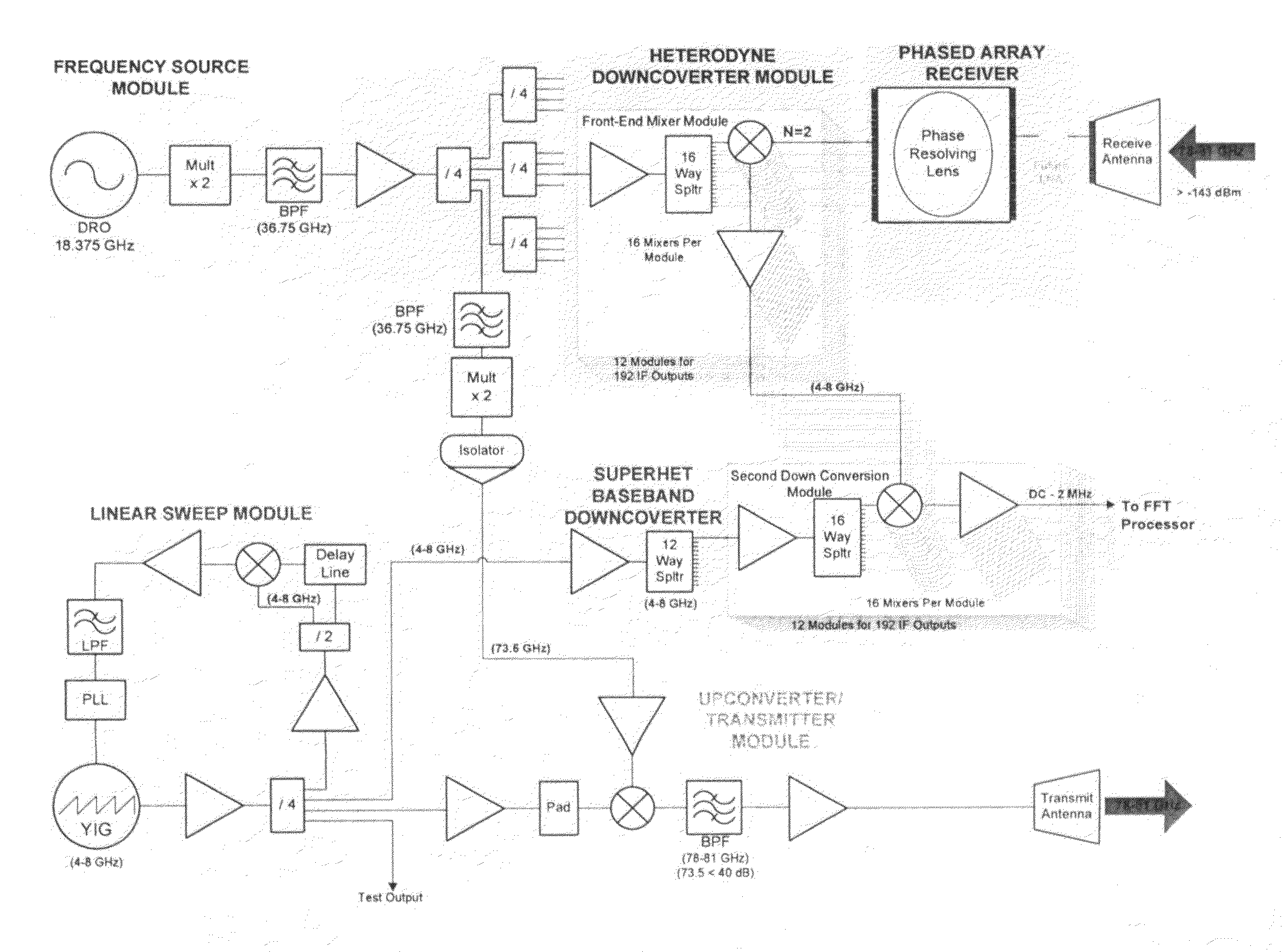
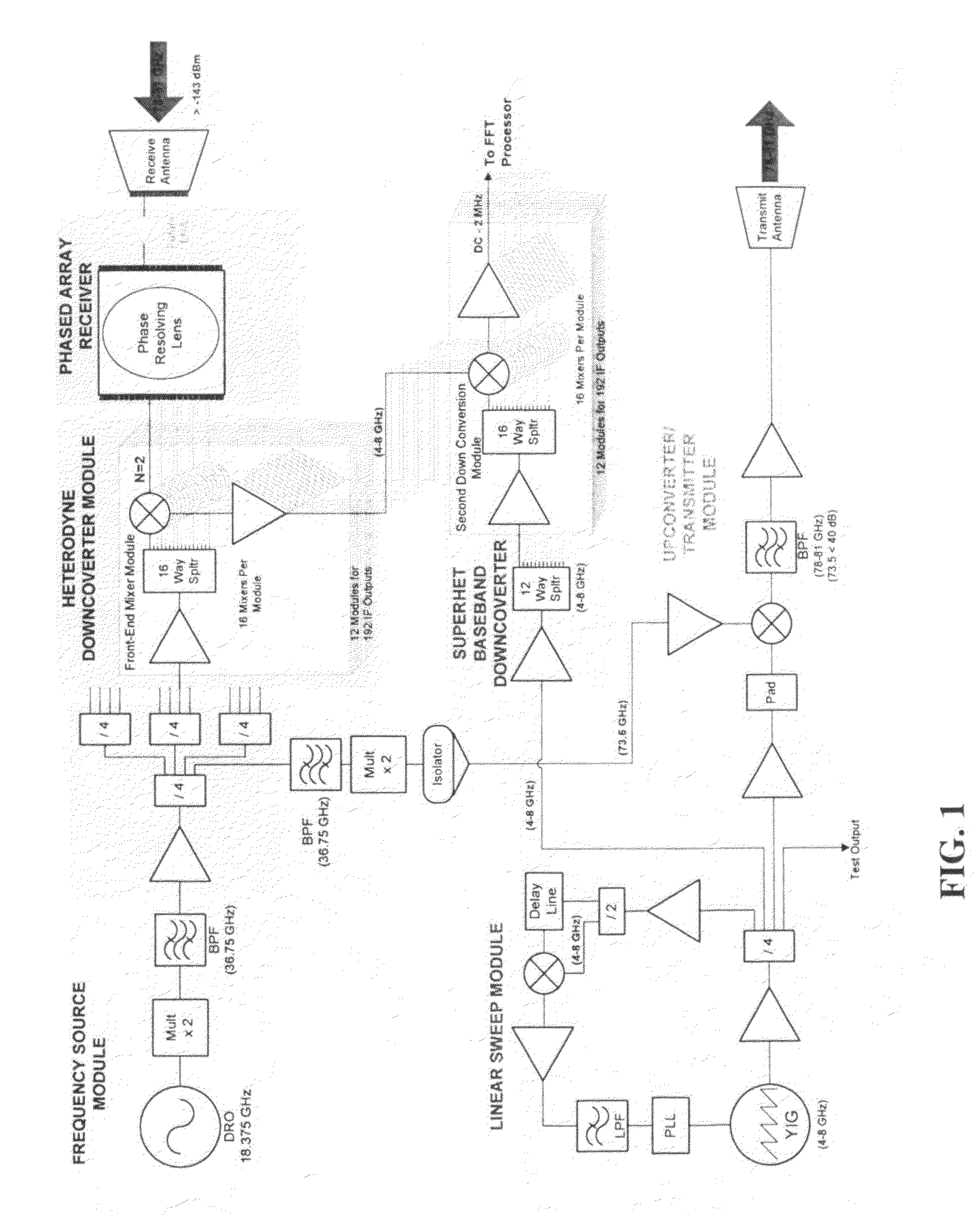
[0030]A block diagram of the FMCW radar system is shown in FIG. 1. The radar system is similar...


PUM


Abstract

An imaging system for a rotary aircraft having a millimeter wave imager with visible or infrared overlay. The system includes an active millimeter wave imaging system comprising a millimeter wave transmitter and a millimeter wave phased array receiver for producing millimeter wave images of a landing region, a second imaging system operating at visible or infrared wavelengths to produce visible or infrared images of the landing region, and a processor programmed with a see and remember algorithm for overlaying the visible or infrared images and the millimeter wave images and to save at least one good high-resolution visible or infrared image in case of a brownout event begins to obscuring the visible or infrared images wherein in case of the brownout event the millimeter wave images are overlaid on the at least one good visible or infrared image and not obscured visible or infrared images.

Description

[0001]This invention relates to imaging radar systems and in particular to millimeter wave imaging radar systems. This application claims the benefit of Provisional Patent Application Ser. No. 60 / 937,867 filed Jun. 29, 2007.BACKGROUND OF THE INVENTION[0002]Rotor wash from a helicopter landing or hovering in ground effect in a dusty or sandy environment can throw enough dust into the air to instantly create zero visibility conditions. According to the US Army Safety Program Aviation Database, from FY2002 to the present there were over 37 Army helicopter accidents attributed to brownout conditions, resulting in multiple deaths and injuries as well as over $181M in equipment damage. A helicopter attempting to land in a desert environment commonly generates an opaque cloud of sand and dust prior to touching down. This is referred to as a “brownout” condition, often leading to disorientation of the pilot and resulting in difficult landings with potential damage to the aircraft and injury...

Claims


Application Information

Patent Timeline
IPC IPC(8): G01S13/89
CPCG01S13/89G01S13/913G01S13/867H01Q25/008G01S13/94G01S13/935
Inventor LOVBERG, JOHNKOLINKO, VLADIMAR
Owner TREX ENTERPRISES CORP
Why Eureka
Try Eureka