Manufacturing Method of High Purity Nickel, High Purity Nickel, Sputtering Target formed from said High Purity Nickel, and Thin Film formed with said Sputtering Target

a technology of high purity nickel and sputtering target, which is applied in the direction of magnetism of inorganic materials, magnetic materials, magnetic bodies, etc., can solve the problems of deterioration of mos-lsi interfacial quality, trouble at the interface bonding area, and inability to manufacture gas components such as carbon and oxygen. , to achieve the effect of efficient manufacturing of high purity nickel

Inactive Publication Date: 2009-01-01
JX NIPPON MINING & METALS CORP
View PDF29 Cites 40 Cited by
  • Summary
  • Abstract
  • Description
  • Claims
  • Application Information

AI Technical Summary

Benefits of technology

[0008]An object of the present invention is to provide a simple method of performing electrolysis employing a solution containing nickel from nickel raw material containing a substantial amount of impurities such as iron, carbon, oxygen and so on, and providing technology on efficiently manufacturing high purity nickel having a purity of 5N (99.999 wt %) or more from such raw material.
[0009]In order to overcome the foregoing problems, the present inventors have discovered that high purity nickel can be manufactured efficiently by eliminating impurities such as iron from anolyte of a solution containing nickel as hydroxide, and employing the impurity-free solution as catholyte.

Problems solved by technology

Alkali metals such as Na and K easily move within the gate insulation film, and cause deterioration of the MOS-LSI interfacial quality.
Meanwhile, transition metal elements such as Fe also cause trouble at the interface bonding area.
Further, gas components such as carbon and oxygen are not preferable in that they cause the generation of particles during sputtering.
Nevertheless, there were problems of inefficiency in that the steps in the method adopting the foregoing solvent extraction process are complex, and it is necessary to give consideration to the safety of the extract agent since a special solvent must be used.

Method used


Image

  • Manufacturing Method of High Purity Nickel, High Purity Nickel, Sputtering Target formed from said High Purity Nickel, and Thin Film formed with said Sputtering Target
  • Manufacturing Method of High Purity Nickel, High Purity Nickel, Sputtering Target formed from said High Purity Nickel, and Thin Film formed with said Sputtering Target

Examples


example 1

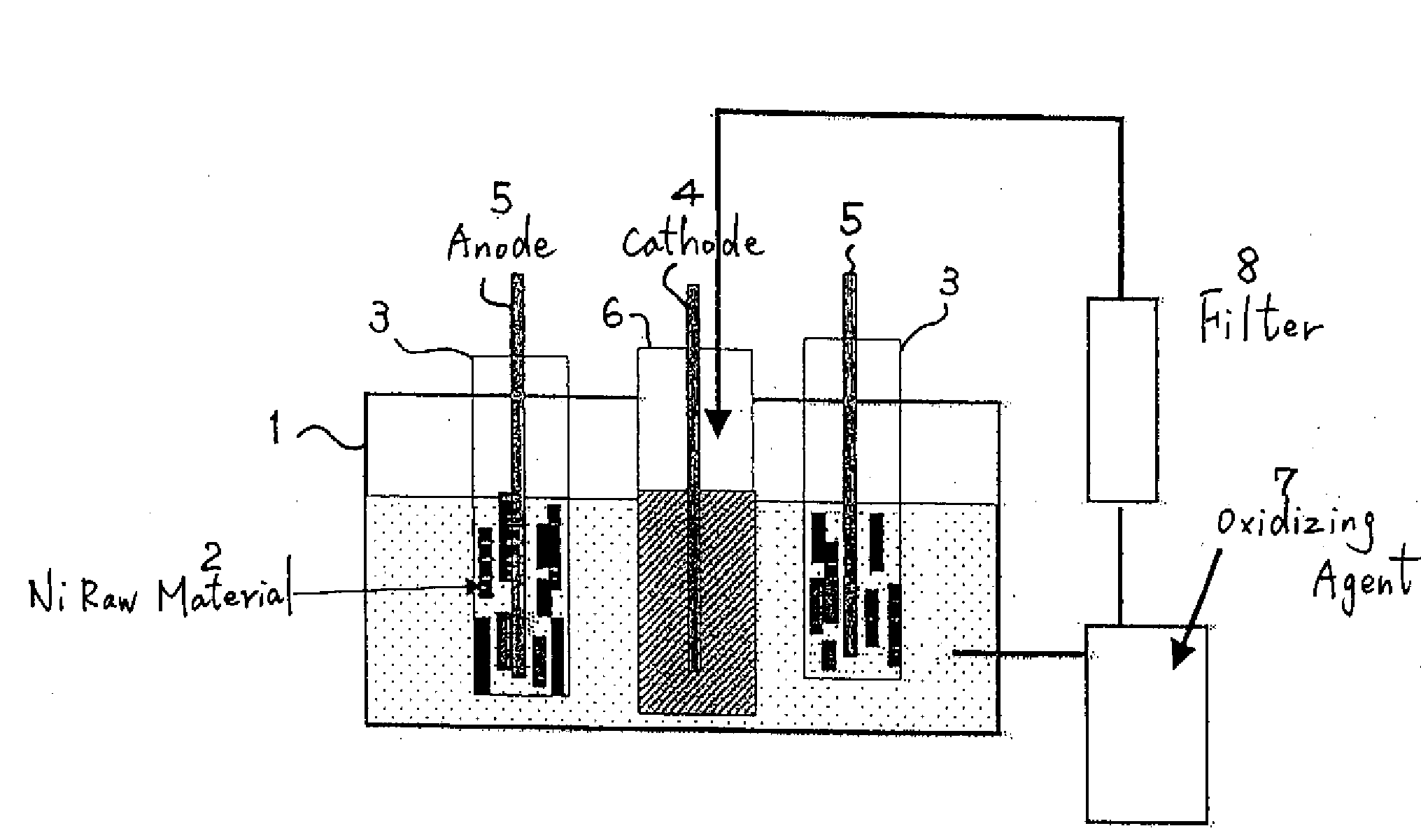
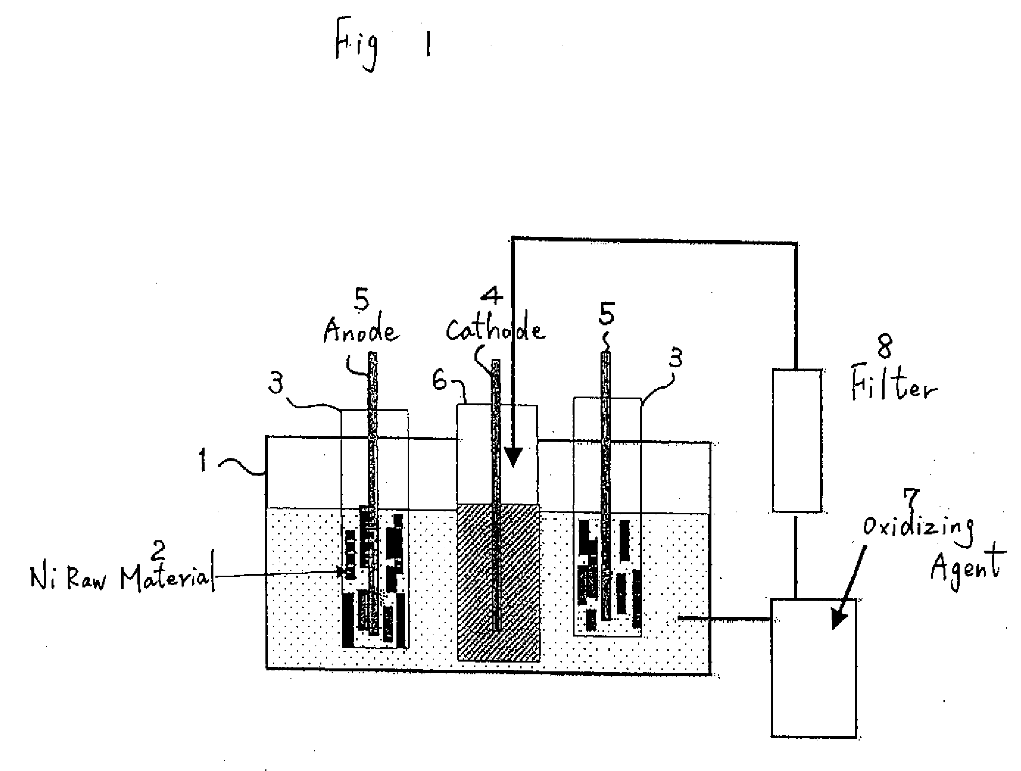
[0030]With the electrolytic bath shown in FIG. 1, 1 kg of massive nickel raw material of a 4N level was made an anode, and electrolysis was performed to a cathode with a nickel plate of a 2N level. The content of impurities in the raw material is shown in Table 1. The nickel raw material mainly contains a great amount of iron, carbon, oxygen, and so on.

[0031]Electrolysis was performed for 40 hr under a bath temperature of 50° C., in which 1 mol / L of hydrofluoric acid was added to a sulfuric acid electrolytic solution, a nickel concentration of 50 g / L and a current density of 2 A / dm2.

[0032]The solution pH was adjusted to 2. Here, anolyte was intermittently extracted. Hydrogen peroxide (H2O2) was added to the extracted anolyte to change the binary iron to ternary iron, and impurities such as iron were precipitated as hydroxide Fe(OH)3.

[0033]Further, impurities such as these sediments were eliminated with an activated carbon filter. According to the above, it was possible to make the c...

example 2

[0036]With the same electrolytic bath as Example 1, massive nickel raw material of a 4N level was made an anode, and electrolysis was performed to a cathode with a nickel plate of a 3N level.

[0037]Electrolysis was performed for 40 hr under a bath temperature of 30° C., with a hydrochloric acid electrolytic solution, a nickel concentration of 80 g / L and a current density of 5 A / dm2.

[0038]As with Example 1, the solution pH was adjusted to 2. Here, anolyte was intermittently extracted. Hydrogen peroxide (H2O2) was added to the extracted anolyte to change the binary iron to ternary iron, and impurities such as iron were precipitated as hydroxide Fe(OH)3.

[0039]Further, impurities such as these sediments were eliminated with an activated carbon filter. According to the above, it was possible to make the concentration of iron within the electrolytic bath to be 1 mg / L or less.

[0040]After the elimination of impurities, this solution was intermittently introduced to the cathode side; that is,...

example 3

[0050]1 kg of massive nickel raw material of a 3N level was made an anode, and electrolysis was performed to a cathode with an aluminum plate of a 2N level. The content of impurities in the raw material is shown in Table 2. The nickel raw material mainly contains a great amount of iron, carbon, copper, carbon, oxygen, and so on.

[0051]Electrolysis was performed for 25 hr under electrolytic conditions of a bath temperature of 40° C., in which 1 mol / L of hydrochloric acid was added to a sulfuric acid electrolytic solution, a nickel concentration of 100 g / L and a current density of 3 A / dm2.

[0052]The solution pH was adjusted to 2.5. Here, anolyte was intermittently extracted. Electrolysis was performed to the extracted anolyte in a preliminary electrolytic bath under a current density of 0.1 A / dm2, and impurities such as iron, cobalt and copper were eliminated.

[0053]Further, organic matter within the electrolytic solution was eliminated with an activated carbon filter. According to the a...


PUM

PropertyMeasurementUnit
pHaaaaaaaaaa
concentrationaaaaaaaaaa
current densityaaaaaaaaaa

Abstract

Upon performing electrolysis with a solution containing nickel as the electrolytic solution, anolyte is adjusted to pH 2 to 5; impurities such as iron, cobalt and copper contained in the anolyte are eliminated by combining any one or two or more of the methods among adding an oxidizing agent and precipitating and eliminating the impurities as hydroxide, eliminating the impurities through preliminary electrolysis, or adding Ni foil and eliminating the impurities through displacement reaction; impurities are thereafter further eliminated with a filter; and the impurity-free solution is employed as catholyte to perform the electrolysis. The present invention relates to a simple method of performing electrolytic refining employing a solution containing nickel from nickel raw material containing a substantial amount of impurities, and provides technology on efficiently manufacturing high purity nickel having a purity of 5N (99.999 wt %) or more.

Description

CROSS REFERENCE TO RELATED APPLICATIONS[0001]This application is a divisional of co-pending U.S. application Ser. No. 10 / 471,112, which is the National Stage of International Application No. PCT / JP01 / 09237, filed Oct. 22, 2001, which claims the benefit under 35 USC §119 of Japanese Application No. 2001-233036, filed Aug. 1, 2001.BACKGROUND OF THE INVENTION[0002]The present invention pertains to a method of manufacturing high purity nickel having a purity of 5N (99.999 wt %) or more through electrolytic refining employing a solution containing nickel, such high purity nickel, a sputtering target formed from the high purity nickel, and a thin film formed with the sputtering target.[0003]Generally speaking, high purity nickel is required to reduce, as much as possible, alkali metals, radioactive elements, transition metal elements and gas components, and is widely used particularly as a sputtering target material for forming VLSI electrodes and wiring or for forming magnetic thin films...

Claims


Application Information

Patent Timeline
Patent Type & Authority Applications(United States)
IPC IPC(8): C23C14/14C23C14/34C25C1/08
CPCC22C19/00Y10T428/12C25C1/08C23C14/3414
Inventor SHINDO, YUICHIROTAKEMOTO, KOUICHI
Owner JX NIPPON MINING & METALS CORP
Why Eureka
Try Eureka