Exhaust gas recirculation system
a technology of exhaust gas and recirculation system, which is applied in the direction of mechanical equipment, non-fuel substance addition to fuel, machines/engines, etc., can solve the problems of increasing the amount of exhaust gas, increasing the temperature of the mixture delivered to the intake manifold, and enlargement of the egr cooler, so as to prevent the reduction of engine combustion efficiency, reduce the amount of air including oxygen delivered in the mixture, and reduce the generation of pm
- Summary
- Abstract
- Description
- Claims
- Application Information
AI Technical Summary
Benefits of technology
Problems solved by technology
Method used
Image
Examples
first embodiment
1. Overall Arrangement
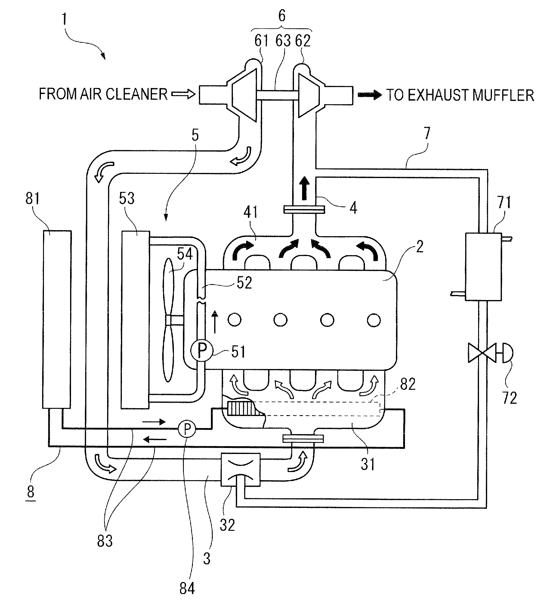
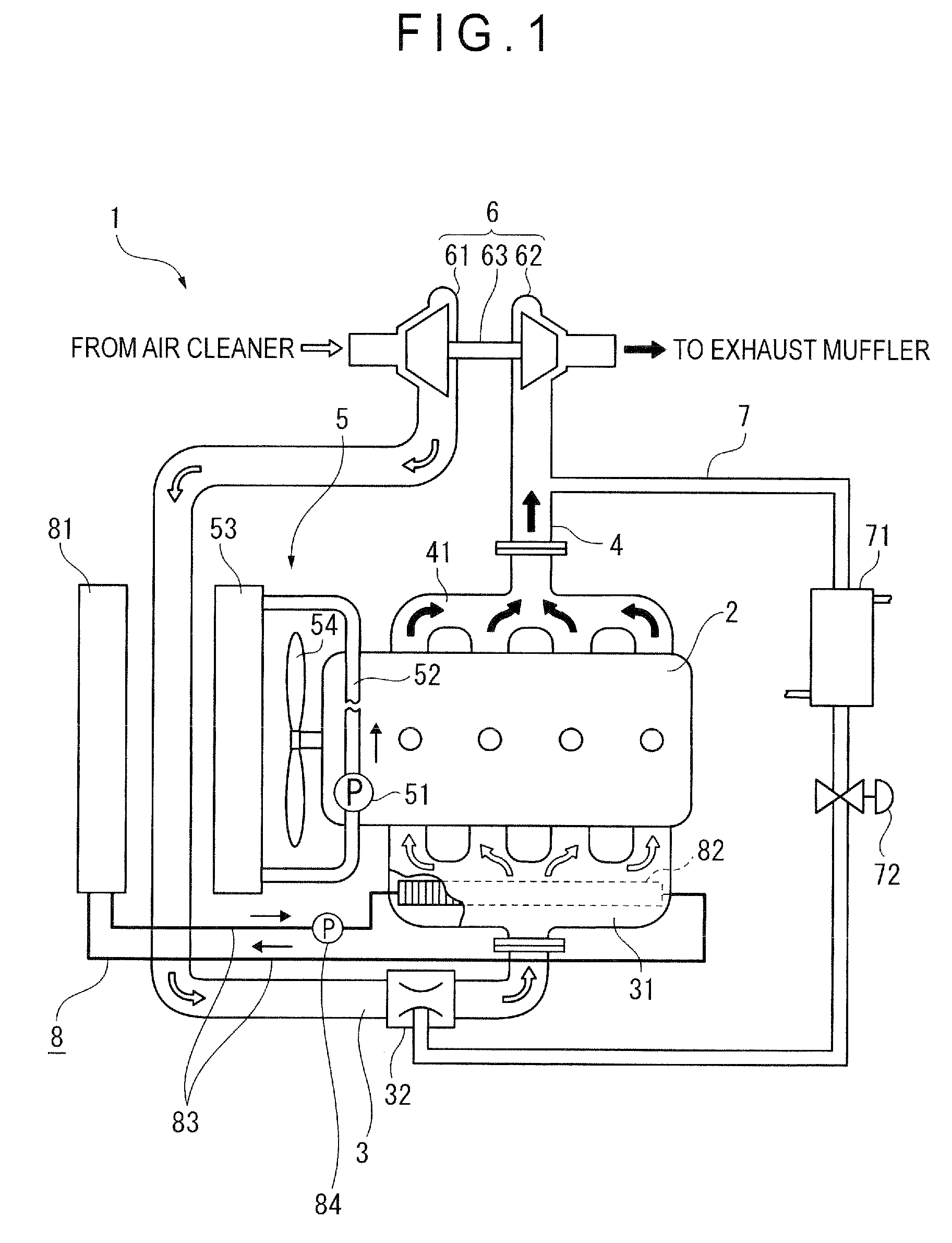
[0034]FIG. 1 is a schematic view showing an EGR system of a diesel engine (internal-combustion engine) 1 according to a first embodiment of the present invention.
[0035]The diesel engine 1 includes an in-line four-cylinder engine body 2, an intake line 3 for delivering gas to a combustion chamber, an exhaust line 4 for exhausting exhaust gas to the exterior of the combustion chamber, and an engine-cooling coolant circulation line 5 for cooling the diesel engine 1. A turbocharger 6 is provided to upstream of the intake line 3 and downstream of the exhaust line 4 in a manner linking the upstream of the intake line 3 and the downstream of the exhaust line 4. It should be noted that the above devices are controlled by an engine controller (not shown in FIG. 1) which outputs controlling signals in accordance with an operator's operation.
[0036]An intake manifold 31 is attached between the intake line 3 and the engine body 2 so that gas from the intake line 3 is distri...
second embodiment
[0066]Next, a second embodiment of the present invention will be described. Note that the same elements as the elements already described are provided with the same numerals and omitted description thereof.
[0067]In the first embodiment, the liquid cooling system 8 is arranged in a circulation of the cooling water independent of the engine-cooling coolant circulation line 5 of the diesel engine 1.
[0068]In contrast, as shown in FIG. 4, the liquid cooling system 18 according to the second embodiment differs from the liquid cooling system 8 in the first embodiment in that: a branch piping line 182 is provided to a portion of the piping line 52; and whereas cooling water of the engine-cooling coolant circulation line 5 of the diesel engine 1 is circulated in the piping line 52, the cooling water is delivered to a heat exchanger 181 through the branch piping line 182 by the pump 51.
[0069]In the embodiments a portion of the cooling water in the engine-cooling coolant circulation line 5 is ...
third embodiment
[0077]Next, a third embodiment of the present invention will be described.
[0078]In the above described first embodiment, the diesel engine 1 is equipped with a single turbocharger 6.
[0079]The third embodiment is different from the first embodiment in that as shown in FIG. 6, the diesel engine 1 is of twin turbo type equipped with double turbochargers 6
[0080]The third embodiment is different from the first embodiment also in that an ATAAC (air to air aftercooler) 33 of air cooling type is provided between the two turbochargers 6.
[0081]In addition to the basic effects described in the first embodiment, compression rate of gas delivered into the intake manifold 31 is increased by the double turbochargers 6 in the third embodiment, thereby improving the combustion rate. Also in the third embodiment, cooling of the intake line 3 is enhanced by the ATAAC 33 provided between the double turbochargers 6, so that temperature of the mixture delivered to the intake manifold 31 can be further lo...
PUM
 Abstract
Description
Claims
Application Information
 - R&D
- Intellectual Property
- Life Sciences
- Materials
- Tech Scout
- Unparalleled Data Quality
- Higher Quality Content
- 60% Fewer Hallucinations
Browse by: Latest US Patents, China's latest patents, Technical Efficacy Thesaurus, Application Domain, Technology Topic, Popular Technical Reports.
© 2025 PatSnap. All rights reserved.Legal|Privacy policy|Modern Slavery Act Transparency Statement|Sitemap|About US| Contact US: help@patsnap.com


