

Electric storage device
a technology of electric storage device and secondary battery, which is applied in the direction of cell components, final product manufacturing, sustainable manufacturing/processing, etc., can solve the problems of reduced energy density of electric storage device, and difficulty in assembly, so as to achieve enhanced energy density and output density
- Summary
- Abstract
- Description
- Claims
- Application Information
AI Technical Summary
Benefits of technology
Problems solved by technology
Method used
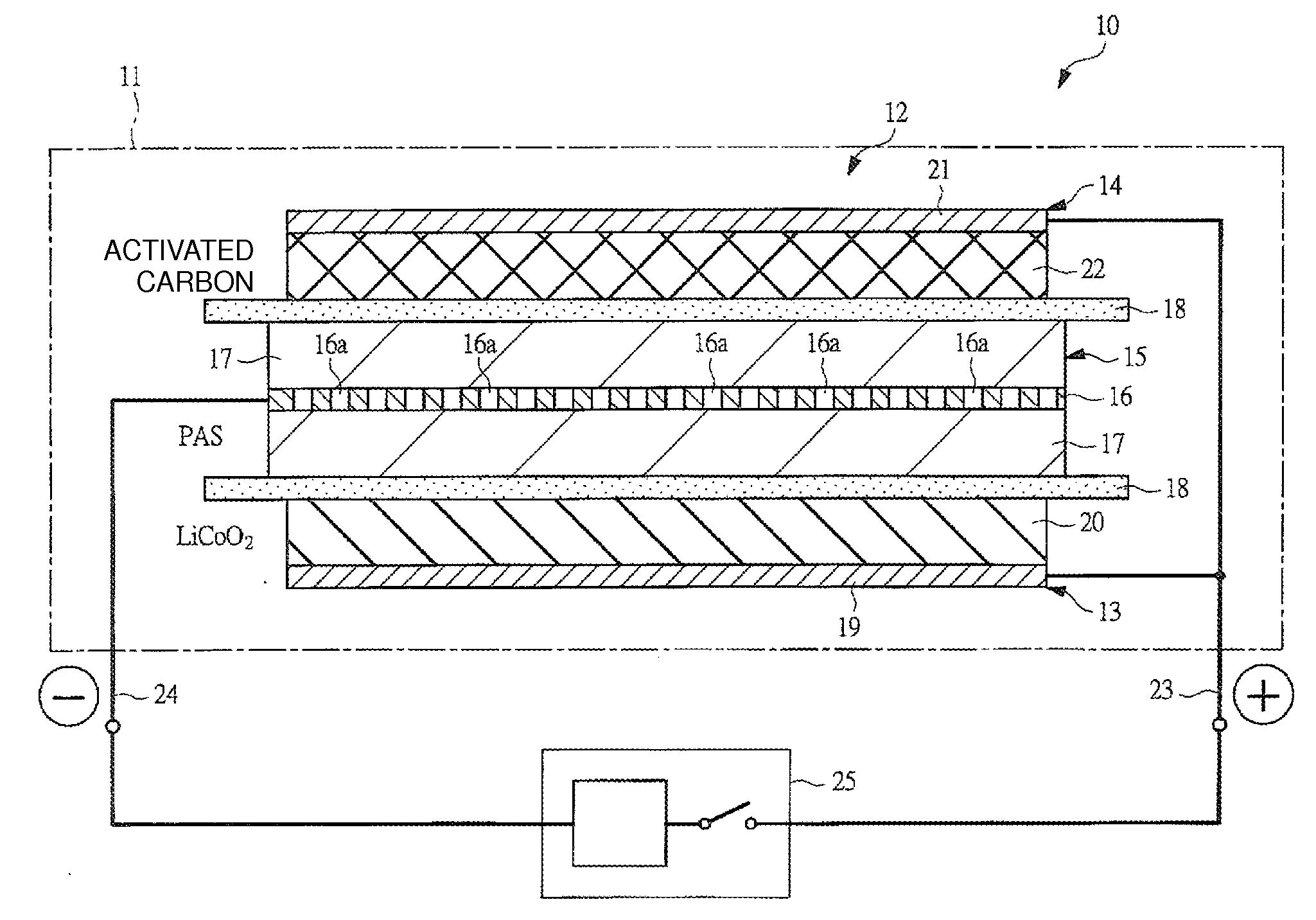
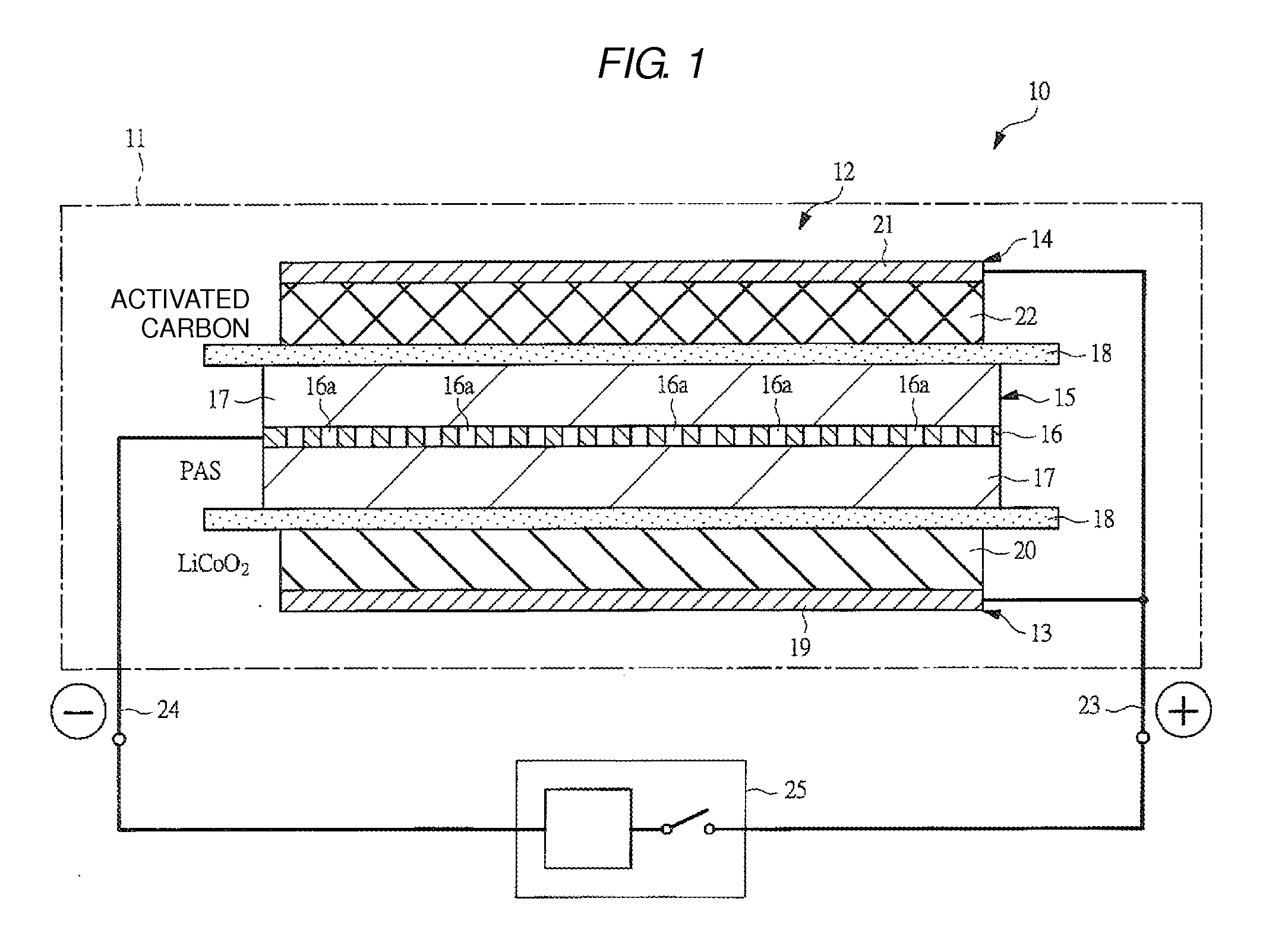
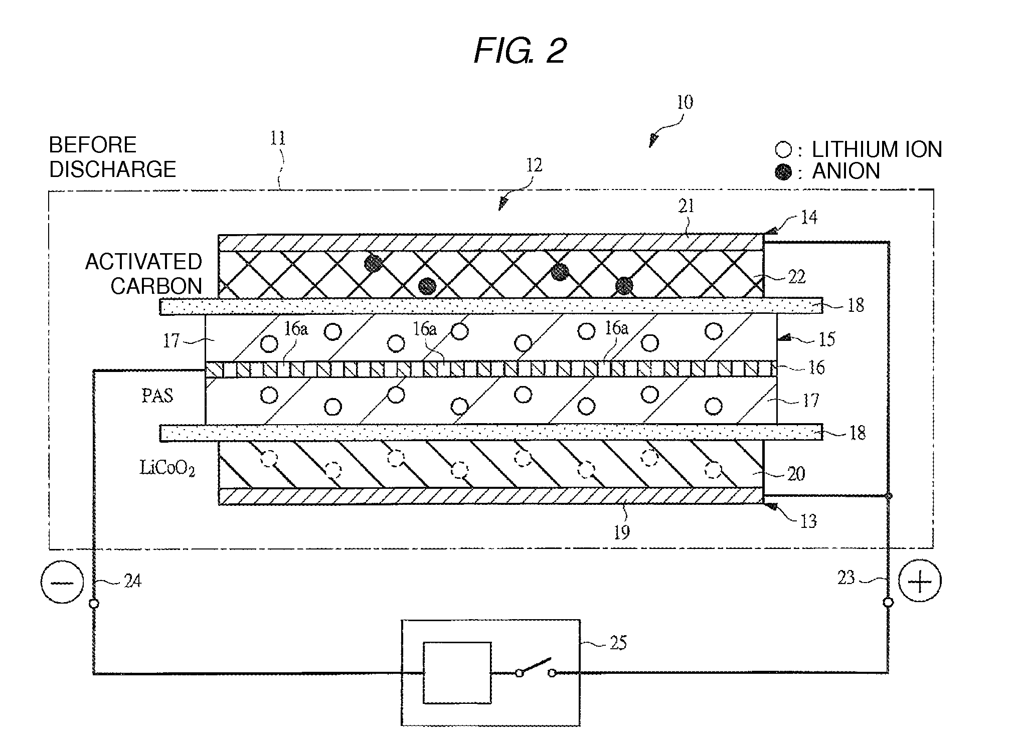
Image

Examples
example 1
Fabrication of Negative Electrode 1
[0071]A phenolic resin molding plate with a thickness of 0.5 mm was put into a Siliconit electric furnace and heat-treated under a nitrogen atmosphere at a rate of 50° C. / hour till temperature reached 500° C., and further heat-treated at the rate of 10° C. / hour till temperature reached 700° C., whereby a PAS plate was synthesized. The PAS plate thus obtained was pulverized with a disc mill to obtain PAS powders. The PAS powders had a H / C ratio of 0.17.
[0072]Then, 100 parts by weight of the above PAS powder and a solution formed by dissolving 10 parts by weight of polyvinylidene fluoride powder in 80 parts by weight of N-methyl pyrrolidone were sufficiently mixed to obtain a slurry 1 for the negative electrode. The slurry 1 for the negative electrode was coated uniformly over both surfaces of a copper expanded metal (manufactured by Nippon Metal Industry Co., Ltd.) having a thickness of 32 μm (porosity of 50%) by a die coater, and dried and pressed,...
example 2
Fabrication of Positive Electrode 3
[0081]A slurry 1 for a positive electrode containing a lithium cobalt oxide was uniformly applied over one surface of the positive-electrode current collector, used in Example 1, by means of a roll coater, and dried. Then, a slurry 2 for a positive electrode containing an activated carbon was uniformly applied over the other surface of the positive-electrode current collector, having the positive-electrode slurry 1 applied, by means of a roll coater, and dried. The applied surfaces were pressed to produce a positive electrode 3 having a thickness of 170 μm. The weight ratio of the lithium cobalt oxide and the activated carbon used for the positive electrode 3 was 1:3.
Fabrication of Electrode Laminate Unit 2
[0082]The negative electrode 1 was cut out into nine pieces, each having an area of 6.0 cm×7.5 cm (excluding the terminal welding parts), and the positive electrode 3 was cut out into eight pieces, each having an area of 5.8 cm×7.3 cm (excluding ...
example 3
Fabrication of Cell 7
[0108]Three hybrid cells 7 were fabricated in the same manner as in Example 1, except that the lithium electrode was not arranged.
Characteristic Evaluation of Cell 7
[0109]The hybrid cell 7 was charged by a constant current-constant voltage charging method for six hours, in which the cell was charged at a constant current of 100 mA till the cell voltage reached 4.0 V and then was charged at a constant voltage of 4.0 V. Then, the cell was discharged at a constant current of 100 mA till the cell voltage reached 2.0 V. The cycle (100 mA discharge) of the charging operation to 4.0 V and the discharging operation to 2.0 V was repeated, and when the cycle was repeated 10 times, the capacitance and the energy density of the cell were evaluated. Subsequently, the cell was charged in a similar way, and was discharged at a constant current of 20 A till the cell voltage reached 2.0 V. The cycle (20 A discharge) of the charging operation to 4.0 V and the discharging operatio...
PUM
 Abstract
Description
Claims
Application Information