Charge air chiller

a technology of air chiller and air compressor, which is applied in the direction of machines/engines, machine operation modes, lighting and heating apparatus, etc., can solve the problems of limiting the charge density, increasing the compression work, and consuming a significant portion of the power/efficiency gain from lower temperature compression in the production of refrigeration, so as to achieve the effect of increasing the boost pressure and/or compression ratio, increasing the energy efficiency, and increasing the efficiency

Inactive Publication Date: 2009-02-05
ERICKSON DONALD CHARLES
View PDF28 Cites 82 Cited by
  • Summary
  • Abstract
  • Description
  • Claims
  • Application Information

AI Technical Summary

Benefits of technology

[0012]The above and other useful objectives are achieved via apparatus and process for chilling internal combustion charge air comprising cooling the charge air to near-ambient temperature, then chilling it to below ambient, and using engine waste heat to power the chiller. The preferred source of at least part of the waste heat is from the heat of compression from the turbocharger, in which case there will be ...

Problems solved by technology

All of these disclosed approaches have the problem that a significant portion of the power/efficiency gain from lower temperature compression is consumed in producing the refrigeration.
First, the exhaust becomes very corrosive when it reaches condensing conditions.
When it is kept above condensing temperature, the temperature of the charge mixture (charge air plus recirculated exhaust) increases, thus increasing the compression work and limiting the charge density.
Conversely, cooling the exhaust below condensing temperature requires costly metallurgy to withstand the corrosive environment in the recirculation path.
Hence, EGR as presently practiced always entails some decrease in efficiency and power.
Too much chilling is required to reduce the charge air temperature to below ambient temperature, which in turn requir...

Method used


Image

  • Charge air chiller
  • Charge air chiller
  • Charge air chiller

Examples


example 1

[0026]A spark-ignited natural gas fueled engine originally has 45° C. charge air, 3.6 bar boost pressure, and compression ratio of 12. The disclosed charge air chiller system is added, providing 10° C. charge air, compression ratio is increased to 15, and boost pressure is decreased to 3.2 bars absolute. Engine efficiency increases by about 6% at full load ISO conditions, and more at warmer ambients.

example 2

[0027]A compression-ignited liquid fueled engine originally has 50° C. charge air, 3.6 bar boost pressure, and compression ratio of 16. After retrofitting a charge air chiller system which provides 15° C. charge air, the compression ratio is increased to 17, and the boost pressure is increased to 3.8 bars absolute.

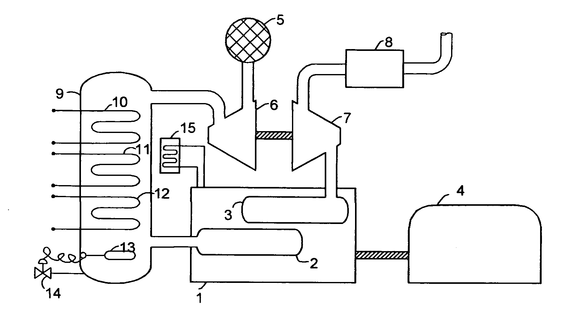
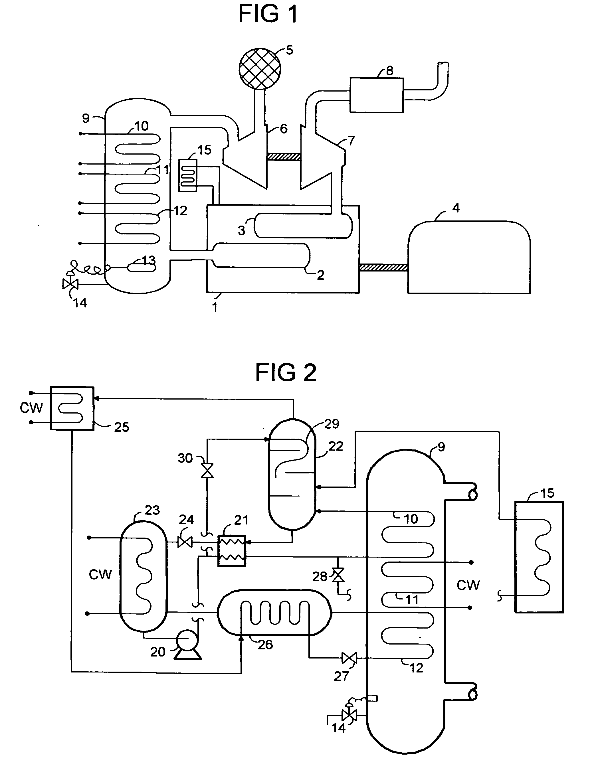
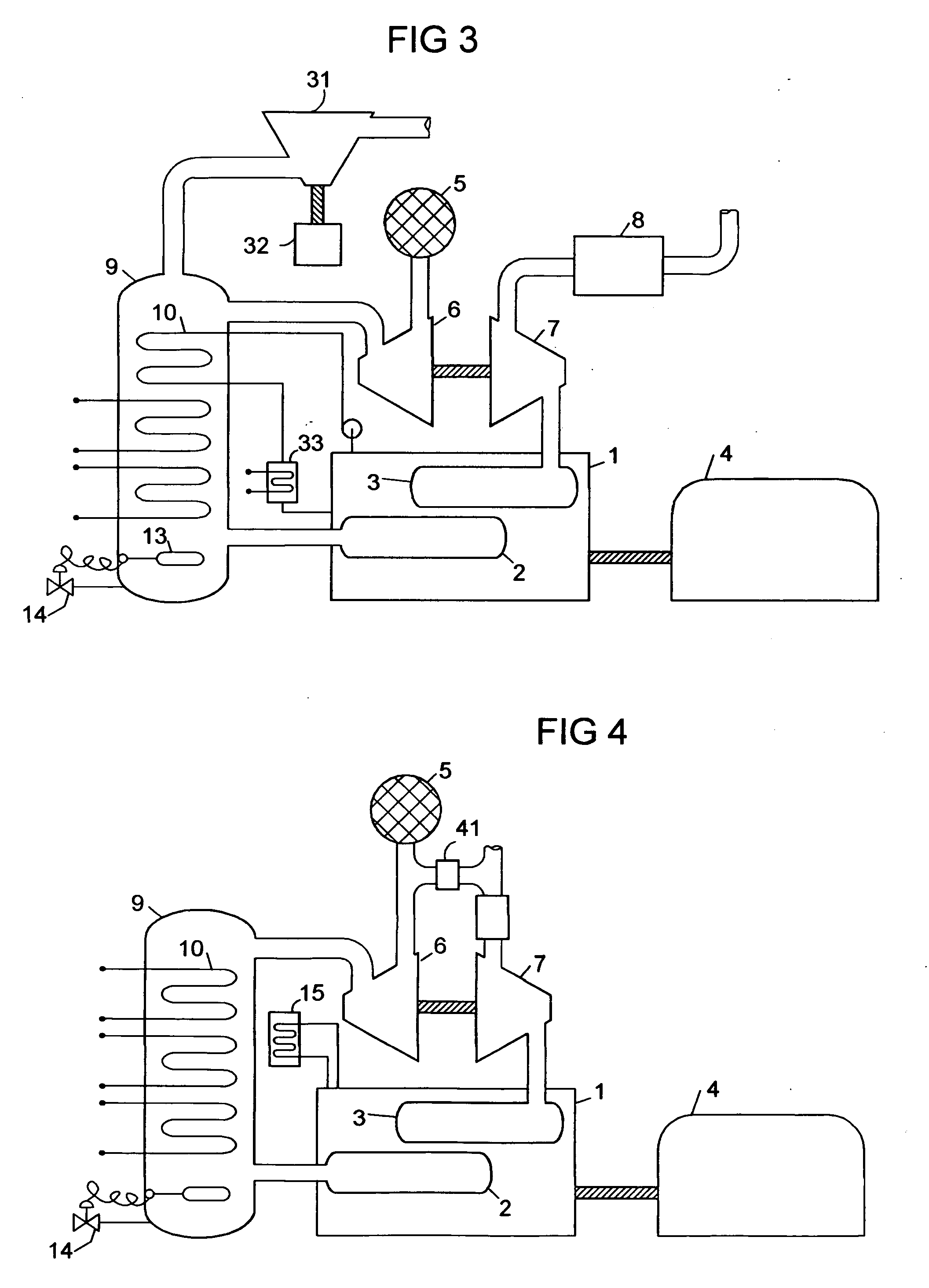
[0028]Referring to FIG. 1, internal combustion engine 1 is comprised of inlet manifold 2, exhaust manifold 3, and the powered apparatus 4, which can variously be an electrical generator, a gas compressor, a transmission, a propeller, or other power-absorbing means. Inlet air from filter 5 is supplied to charge compressor 6, which is powered for example by exhaust powered turbine 7. Exhaust treatment apparatus 8 accomplishes any required modifications of the exhaust stream, such as emissions reduction, heat recovery, and silencing. The charge air is supplied to an intercooler system comprised of pressure containment 9 plus three heat exchange segments which are arranged seq...


PUM


Abstract

A system for chilling the pressurized charge air to a reciprocating engine is disclosed wherein the chilling is provided by a thermally activated refrigeration cycle powered by waste heat from the engine system. This reduces the required compression power, and also retards knock, making higher compression ratios possible. The chilling system is designed to minimize the amount of chilling required, and also to enable use of compression heat to power the chiller. The disclosed improvement also accommodates exhaust gas recirculation, plus providing activation heat from the exhaust gas, plus Miller cycle timing of the intake valves. Referring to FIG. 1, the charge air from turbocharger 5 is cooled in three stages: heat recovery stage 10; ambient-cooled stage 11; and chilling stage 12. Condensed moisture is removed from the charge air by valve 14 before the charge is supplied to inlet manifold 2.

Description

CROSS REFERENCE TO RELATED APPLICATIONS[0001]NASTATEMENT REGARDING FEDERALLY SPONSORED RESEARCH OR DEVELOPMENT[0002]NABACKGROUND OF THE INVENTION[0003]An intercooler system for an internal combustion engine is designed to provide subambient temperature charge air without mechanical refrigeration, and preferably without the complications of powering the refrigeration system with exhaust combustion gas heat.[0004]The advantage of chilling engine inlet air, whether from the atmosphere or from a turbocharger / supercharger, are well documented in the prior art. Compression energy varies approximately with the absolute temperature, and less energy to compression means more useful energy out, e.g. higher efficiency. With a turbocharger / supercharger and conventional intercooler, the charge air is well above ambient temperature. The prior art discloses many ways of chilling the inlet or charge air to below ambient temperature. Most involve mechanical power input of one sort or another. For ex...

Claims


Application Information

Patent Timeline
IPC IPC(8): F02B29/04F25B27/02F25B7/00
CPCF02B1/12F02B29/0412F02B29/0443F02B37/00F02B2275/32F02M25/0718Y02T10/16F02M25/0739F25B15/04F25B27/02Y02T10/146Y02T10/142F02M25/0727F02M26/15F02M26/23F02M26/34Y02A30/274Y02T10/12
Inventor ERICKSON, DONALD CHARLES
Owner ERICKSON DONALD CHARLES
Why Eureka
Try Eureka