
Negative electrode current collector for lithium ion secondary battery, negative electrode for lithium ion secondary battery, and lithium ion secondary battery

a lithium ion secondary battery and negative electrode technology, applied in the direction of electrochemical generators, cell components, cell components, etc., can solve the problems of generating joule's heat, generating large amounts of heat, and batteries using alloy-type negative electrode active materials, etc., to achieve high power and high capacity

Inactive Publication Date: 2009-02-12
PANASONIC CORP
View PDF10 Cites 13 Cited by
  • Summary
  • Abstract
  • Description
  • Claims
  • Application Information

AI Technical Summary

Benefits of technology

[0012]An object of the invention is to provide a lithium ion secondary battery including an alloy-type negative electrode active material and having high capacity, high power, and long life, wherein even under abnormal conditions such as an internal short-circuit, the battery does not produce large heat and is unlikely to heat up to a high temperature.
[0025]The lithium ion secondary battery of the invention including the negative electrode of the invention has high capacity, high power, excellent battery performance such as cycle characteristics, and long battery life. Also, the lithium ion secondary battery of the invention has a very high level of safety despite the use of a high-capacity alloy-type negative electrode active material. For example, even if an internal short-circuit occurs, it is unlikely to expand, and the heat generation is markedly suppressed.

Problems solved by technology

However, batteries using alloy-type negative electrode active materials have a problem to be solved.
That is, in the event of an internal short-circuit, they produce large amounts of heat and tend to heat up to high temperatures.
First, the nail causes an internal short-circuit between the positive and negative electrodes, thereby generating Joule's heat.
The amount of heat generation is particularly large in the contact area of the nail and the current collectors of the positive and negative electrodes, having low resistance.
However, the heat generation causes the separator to shrink, which in turn causes a short-circuit between the active material layers of the positive and negative electrodes.
At this time, when the negative electrode active material is an alloy-type negative electrode active material, a large amount of heat is locally generated, and the battery tends to heat up to a high temperature.
Also, when an alloy-type negative electrode active material absorbs lithium, it expands due to a large change in crystal structure, thereby causing a plastic deformation of the negative electrode current collector, such as wrinkles or warpage of the negative electrode current collector.
The deformation of the negative electrode current collector also causes deformation of the negative electrode.
Excessive deformation of the negative electrode current collector and the negative electrode causes a series of problems, such as separation of the negative electrode active material layer from the negative electrode current collector, a decrease in electronic conductivity between the negative electrode current collector and the negative electrode active material layer, degradation of battery performance such as cycle characteristics.
However, merely forming the protrusions and depressions on the negative electrode current collector surface does not permit reduction or prevention of significant heat generation in the event of an internal short-circuit of the battery.
However, even the use of the negative electrode disclosed by this conventional technique does not permit reduction or prevention of significant heat generation in the event of an internal short-circuit of the battery.

Method used


Image

  • Negative electrode current collector for lithium ion secondary battery, negative electrode for lithium ion secondary battery, and lithium ion secondary battery
  • Negative electrode current collector for lithium ion secondary battery, negative electrode for lithium ion secondary battery, and lithium ion secondary battery
  • Negative electrode current collector for lithium ion secondary battery, negative electrode for lithium ion secondary battery, and lithium ion secondary battery

Examples


example 1

(1) Preparation of Positive Electrode

[0121]A positive electrode mixture paste was prepared by sufficiently mixing 10g of lithium cobaltate (LiCoO2), 0.3 g of acetylene black (conductive agent), 0.8 g of polyvinylidene fluoride powder (binder), and 5 ml of N-methyl-2-pyrrolidone (NMP). This positive electrode mixture paste was applied onto one face of a 20-μm thick aluminum foil (positive electrode current collector), dried, and rolled to form a positive electrode active material layer. This was then cut into a square of 30 mm×30 mm, to obtain a positive electrode.

[0122]In the positive electrode thus obtained, the positive electrode active material layer carried on one face of the aluminum foil had a thickness of 70 μm and a size of 30 mm×30 mm. An aluminum positive electrode lead was connected to the face of the aluminum foil opposite the face on which the positive electrode active material layer was formed.

(2) Preparation of Negative Electrode

[0123]A rolled copper foil (thickness 3...

example 2

[0136]In the same manner as in Example 1, a negative electrode active material layer was formed as an aggregate of columns formed on the surfaces of the protrusions on the surface of the negative electrode current collector, except that among the deposition conditions of the negative electrode active material, the oxygen flow rate from the nozzle was set to 29 sccm, the angle α to 56°, and the deposition time to 35 minutes. These columns were grown slantwise relative to the direction perpendicular to the surface of the negative electrode current collector. The thickness of the negative electrode active material layer was 20 μm, and the volume ratio A / B was 1.6 or more. Also, the composition of the compound constituting the negative electrode active material layer was SiO0.7.

[0137]Next, under the same conditions as those of Example 1, lithium metal was deposited on the surface of the negative electrode active material layer, to produce a negative electrode (not subjected to a corruga...

example 3

[0138]In the same manner as in Example 1, a negative electrode active material layer was formed as an aggregate of columns formed on the surfaces of the protrusions on the surface of the negative electrode current collector, except that among the deposition conditions of the negative electrode active material, the oxygen flow rate from the nozzle was set to 32 sccm, the angle α to 530, and the deposition time to 31 minutes. These columns were grown slantwise relative to the direction perpendicular to the surface of the negative electrode current collector. The thickness of the negative electrode active material layer was 20 μm, and the volume ratio A / B was 1.6 or more. Also, the composition of the compound constituting the negative electrode active material layer was SiO0.7.

[0139]Next, under the same conditions as those of Example 1, lithium metal was deposited on the surface of the negative electrode active material layer, to produce a negative electrode (not subjected to a corruga...


PUM


Abstract

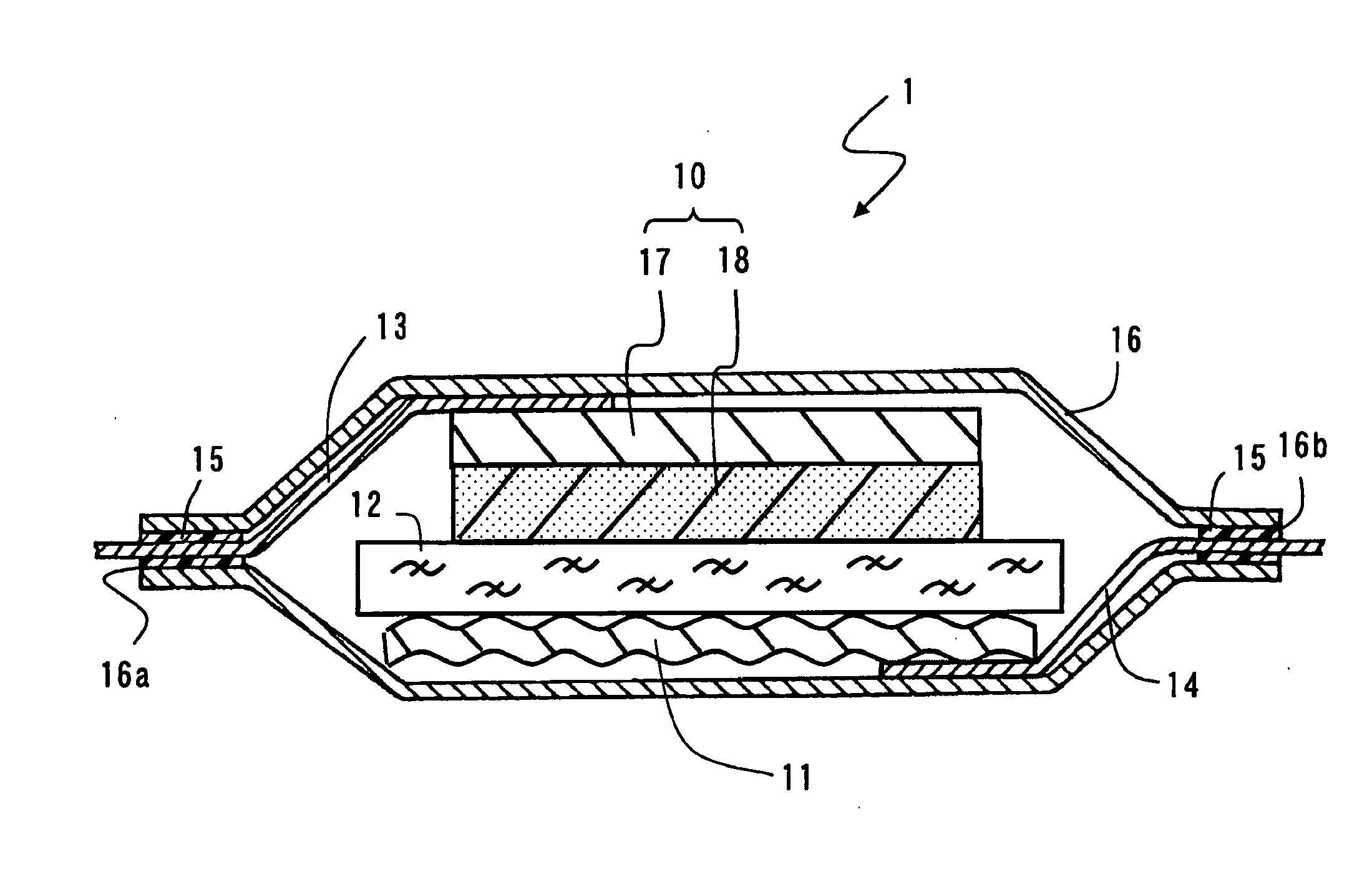
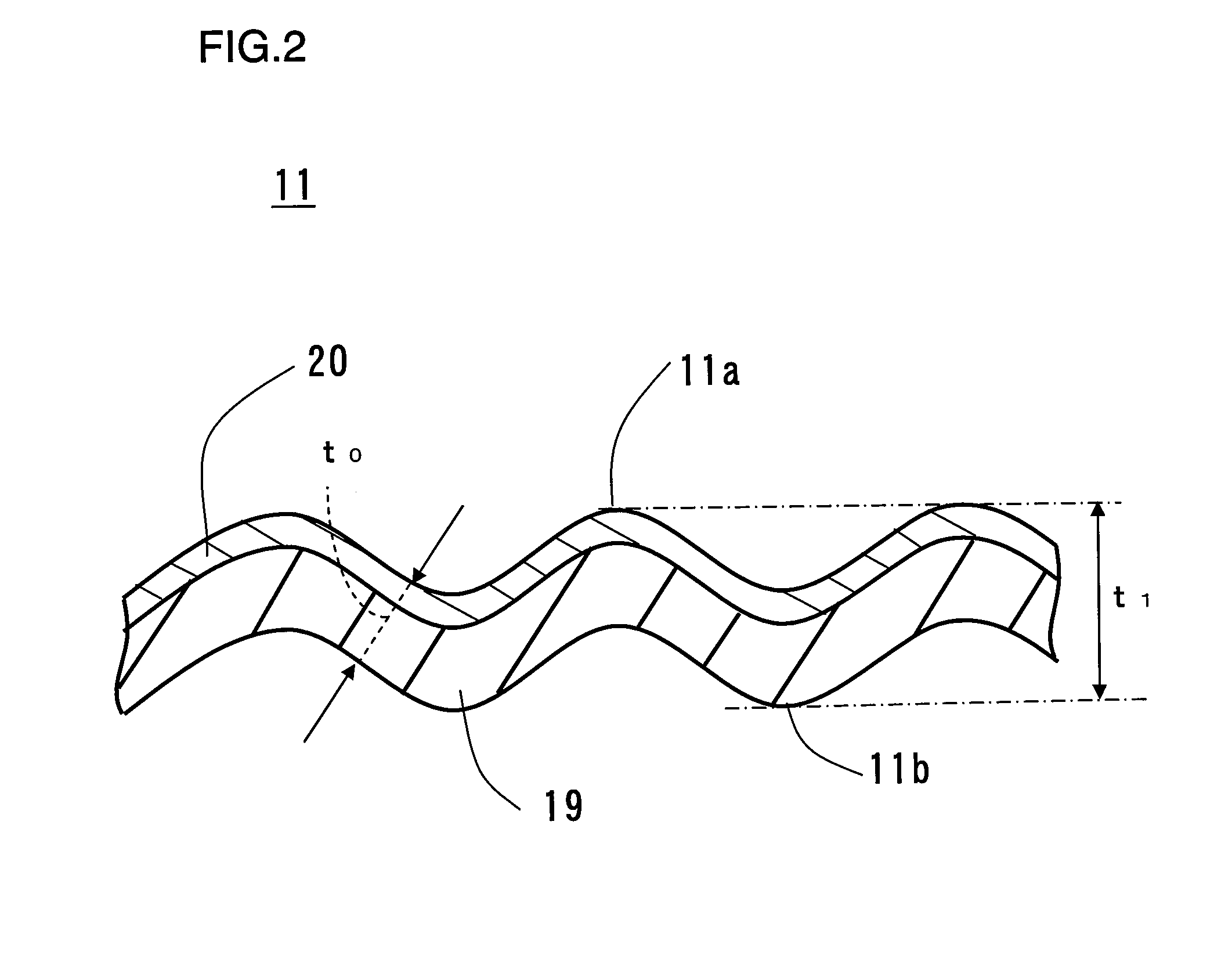
A lithium ion secondary battery includes a negative electrode that is shaped like waves in a section in the thickness direction. In the negative electrode, the ratio t1 / t0 of the largest thickness t1 to the smallest thickness t0 is from 1.2 to 3.0. The negative electrode includes a thin-film negative electrode active material layer in which the ratio A / B of the volume A in a charged state to the volume B in a discharged state is 1.2 or more. The lithium ion secondary battery has high capacity, high power, long life, and improved safety. In particular, heat generation due to an internal short-circuit is significantly suppressed in a nail penetration test.

Description

FIELD OF THE INVENTION[0001]The invention relates to a negative electrode current collector for a lithium ion secondary battery, a negative electrode for a lithium ion secondary battery, and a lithium ion secondary battery. More particularly, the invention mainly relates to improvements in the negative electrode.BACKGROUND OF THE INVENTION[0002]Lithium ion secondary batteries have high capacity and high energy density, and their size and weight can be easily reduced. Thus, they are widely used as the power source for portable small-sized electronic devices. Examples of portable electronic devices include cellular phones, personal digital assistants (PDAs), notebook personal computers, video cameras, and portable game machines.[0003]A typical lithium ion secondary battery includes an electrode assembly composed of: a positive electrode comprising a positive electrode active material layer containing a lithium cobalt compound and formed on the surface of an aluminum foil (positive ele...

Claims


Application Information

Patent Timeline
Patent Type & Authority Applications(United States)
IPC IPC(8): H01M4/02H01M10/00H01M4/13H01M4/134H01M4/136H01M4/58H01M10/052H01M10/0525
CPCH01M4/0421H01M4/131H01M4/134H01M4/136H01M4/139Y02E60/122H01M4/1395H01M4/1397H01M4/70H01M10/052H01M10/0585H01M4/1391Y02E60/10
Inventor FUJIKAWA, MASATOTAKEZAWA, HIDEHARUKASAMATSU, SHINJIYOKOYAMA, TOMOHIKO
Owner PANASONIC CORP
Learn More