
Method and device for controlling exhaust emission from internal combustion engine

a technology of internal combustion engine and purification method, which is applied in the direction of machines/engines, metal/metal-oxide/metal-hydroxide catalysts, arsenic compounds, etc., can solve the problems of increasing the pressure of the filter, and achieve stable combustion reaction, filter regeneration stably, and filter regeneration

Active Publication Date: 2009-03-05
UMICORE SHOKUBAI USA +1
View PDF18 Cites 5 Cited by
  • Summary
  • Abstract
  • Description
  • Claims
  • Application Information

AI Technical Summary

Benefits of technology

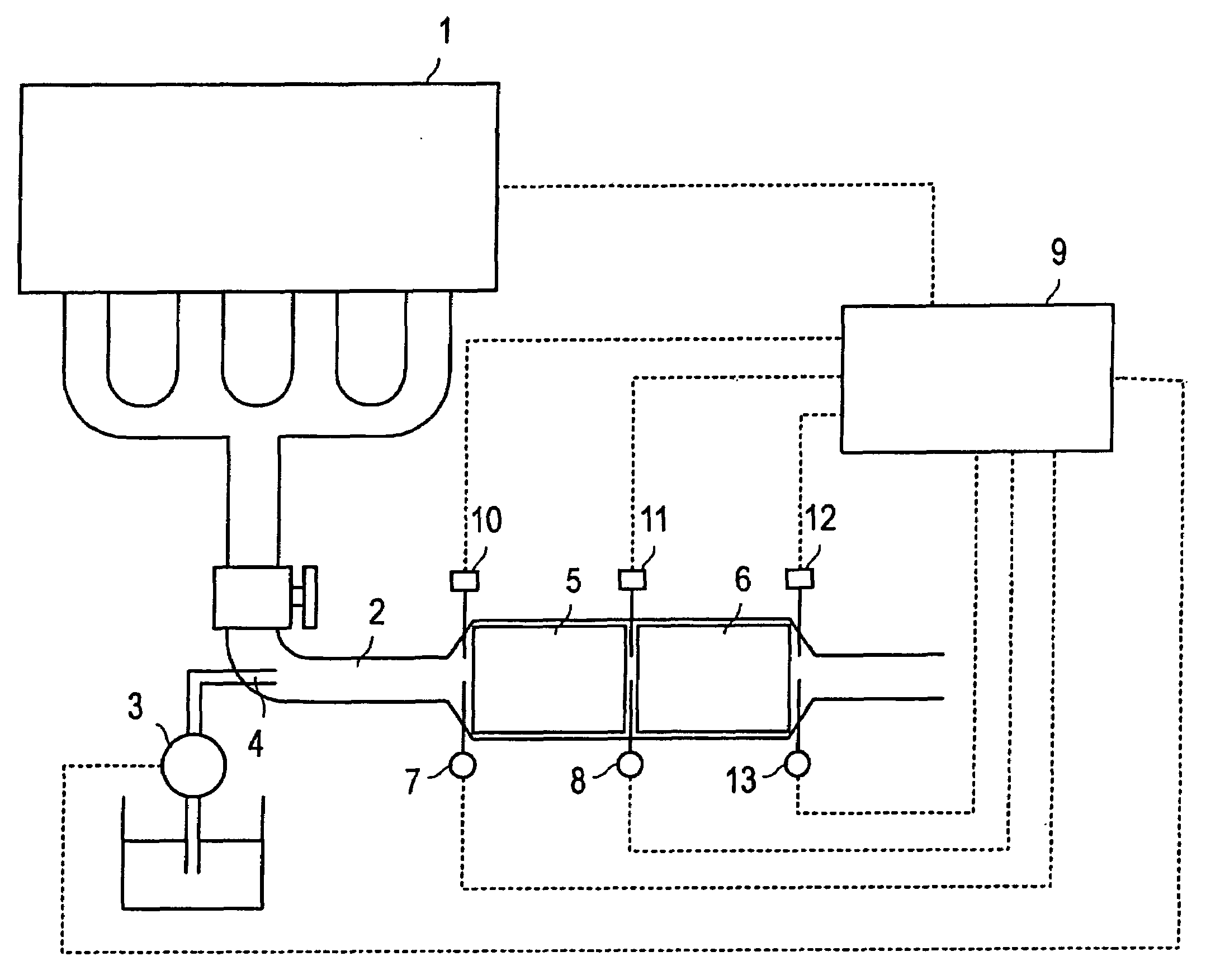
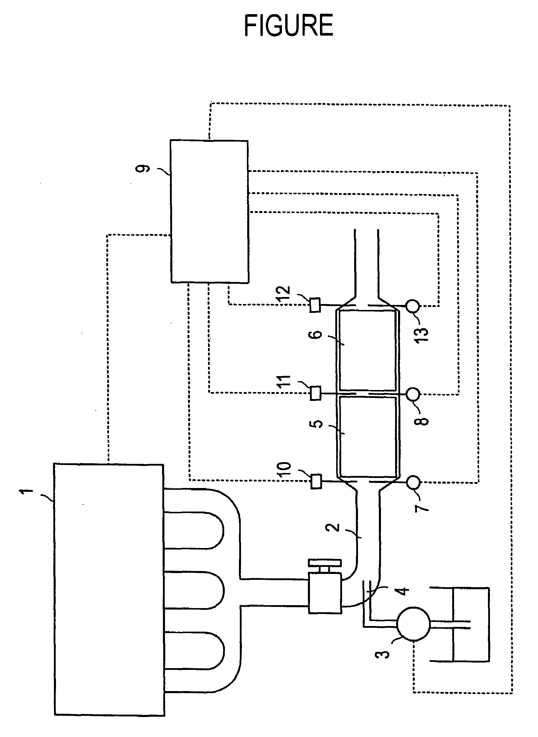
[0021]The present invention is one having the above composition, and using a catalyst containing both platinum and palladium, as an oxidation catalyst, therefore, a system for supplying high concentration hydrocarbon-based fuel, which is thus capable of filter regeneration stably for a long period; in particular, by presence of both platinum and palladium in suitable ratio, effect thereof becomes excellent. In addition, this effect makes to occur difficult adherence of carbon-containing components such as hydrocarbons, and enables a stable combustion reaction, and enables filter regeneration stably for a long period.

Problems solved by technology

However, accumulated PM causes an increase of pressure in the filter.

Method used


Image

  • Method and device for controlling exhaust emission from internal combustion engine
  • Method and device for controlling exhaust emission from internal combustion engine

Examples


example 1

[0048]Into 25 g of activated alumina (γ-Al2O3 with a BET specific surface area of 150 m2 / g, and an average primary particle diameter of 75 μm), 1 ml of a deionized water solution (hereafter, deionized water was used in any of an aqueous solution) of palladium nitrate containing 0.2 g of palladium, an aqueous solution (a concentration of 14% by mass) were impregnated, followed by drying at 120° C. for 8 hours, and firing at 500° C. for 1 hour. Then, 25 g of the resultant powders, 42 ml of an aqueous solution of platinum nitrate containing 4.8 g of platinum, 70 g of activated alumina (γ-Al2O3 with a BET specific surface area of 300 m2 / g, and an average primary particle diameter of 75 μm), and 30 g of zeolite (BEA type, with silica / alumina ratio=25, an average particle diameter of 10.5 μm) were wet-milled by a ball mill, to prepare aqueous slurry. This slurry was wash-coated onto 1 litter of a honeycomb carrier made of cordierite, having 400 cells per in2 of the cross-sectional area, f...

example 2

[0049]An oxidation catalyst (B) was obtained in the same way as Example 1, except that 4 ml of an aqueous solution of palladium nitrate containing 0.8 g of palladium was used instead of 1 ml of an aqueous solution of palladium nitrate containing 0.2 g of palladium, and 37.2 ml of an aqueous solution of platinum nitrate containing 4.2 g of platinum was used instead of 42 ml of an aqueous solution of platinum nitrate containing 4.8 g of platinum.

example 3

[0050]An oxidation catalyst (C) was obtained in the same way as Example 1, except that 8.5 ml of an aqueous solution of palladium nitrate containing 1.7 g of palladium was used instead of 1 ml of an aqueous solution of palladium nitrate containing 0.2 g of palladium, and 29.2 ml of an aqueous solution of platinum nitrate containing 3.3 g of platinum was used instead of 42 ml of an aqueous solution of platinum nitrate containing 4.8 g of platinum.


PUM

PropertyMeasurementUnit
temperatureaaaaaaaaaa
mass ratioaaaaaaaaaa
temperatureaaaaaaaaaa

Abstract

The present invention provides a purification method excellent also in removing particulates or the like from exhaust gas from an internal combustion engine, in particular, a diesel engine or the like. A purification method for exhaust gas from an internal combustion engine, wherein said purification method uses an exhaust gas purification apparatus comprising an oxidation zone installed with an oxidation catalyst supporting both platinum and palladium, and a filtering zone installed with a particulate filter, along exhaust gas flow at the exhaust gas passage of an internal combustion engine, characterized in that hydrocarbon-based liquid is supplied to the inflow side of the exhaust gas of said oxidation zone at the time when 2 to 10 g of particulates per 1 litter of said particulate filter are caught, to raise temperature of said exhaust gas up to equal to or higher than 550° C. by said oxidation catalyst so as to make the residue of said particulate filter combusted; and an apparatus thereof.

Description

TECHNICAL FIELD[0001]The present invention relates to a purification method and a device for exhaust gas which emitted from an internal combustion engine. If we go into detail, the present invention relates to an excellent purification method for harmful component like particulates in the exhaust gas emission from internal combustion engine, in particular, a diesel engine.BACKGROUND ART[0002]A diesel particulate filter is used to catch PM (particulate matter) containing dark smoke or SOF (soluble organic fraction) exhausted from an internal combustion engine such as a diesel engine or the like. However, accumulated PM causes an increase of pressure in the filter.[0003]Therefore, to prevent an increase of pressure, a heating unit such as an electric heater is equipped around the filter to combust and remove PM so as to regenerate the filter.[0004]Such a conventional purification apparatus for exhausted gas, however, required to switch a filter to another one while the regeneration of...

Claims


Application Information

Patent Timeline
Patent Type & Authority Applications(United States)
IPC IPC(8): F01N3/035
CPCB01D53/944B01D2251/208B01D2255/102B01D2258/012B01J23/44F01N13/0097B01J37/0246F01N3/0231F01N3/0253F01N3/035F01N2610/03B01J29/7007F01N3/02F01N3/20F01N3/10B01D53/94
Inventor IKEDA, MASANORIFUKUMOTO, ATSUSHI
Owner UMICORE SHOKUBAI USA
Learn More