Power control method of high frequency dielectric heating and apparatus thereof

Inactive Publication Date: 2009-03-12
PANASONIC CORP
View PDF3 Cites 17 Cited by
  • Summary
  • Abstract
  • Description
  • Claims
  • Application Information

AI Technical Summary

Benefits of technology

[0037]According to the invention, the structure of the heating apparatus can be simplified and thus the apparatus can be reduced in size. Also, there is eliminate

Problems solved by technology

As a result of this, when the temperature of the heater is maintained within a proper range, the heating output of the magnetron can be varied only in a very small range, which makes it impossible to vary the heating output continuously.
Owing to this, it has been found that the wave form shaping is not able to follow variations in the characteristics of magnetrons, kinds of magnetrons, variations in ebm (a voltage between anode and cathode) due to the te

Method used


Image

  • Power control method of high frequency dielectric heating and apparatus thereof
  • Power control method of high frequency dielectric heating and apparatus thereof
  • Power control method of high frequency dielectric heating and apparatus thereof

Examples


embodiment 1

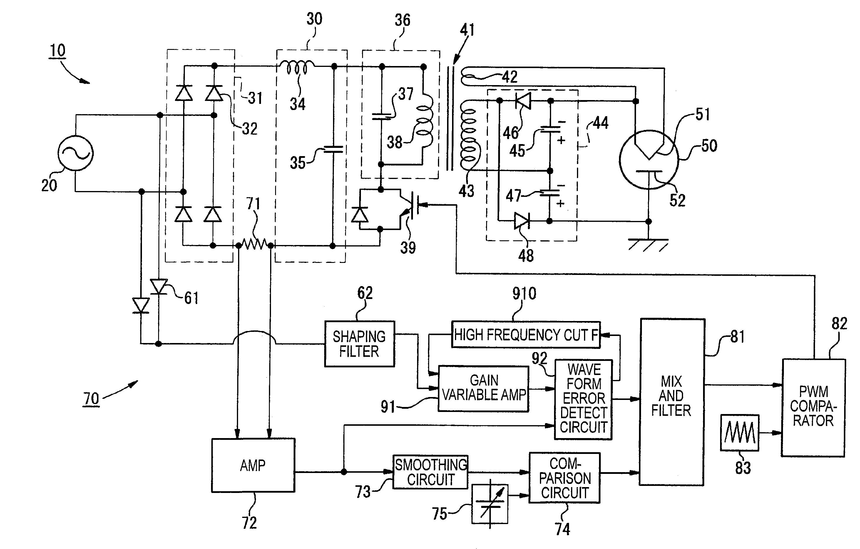
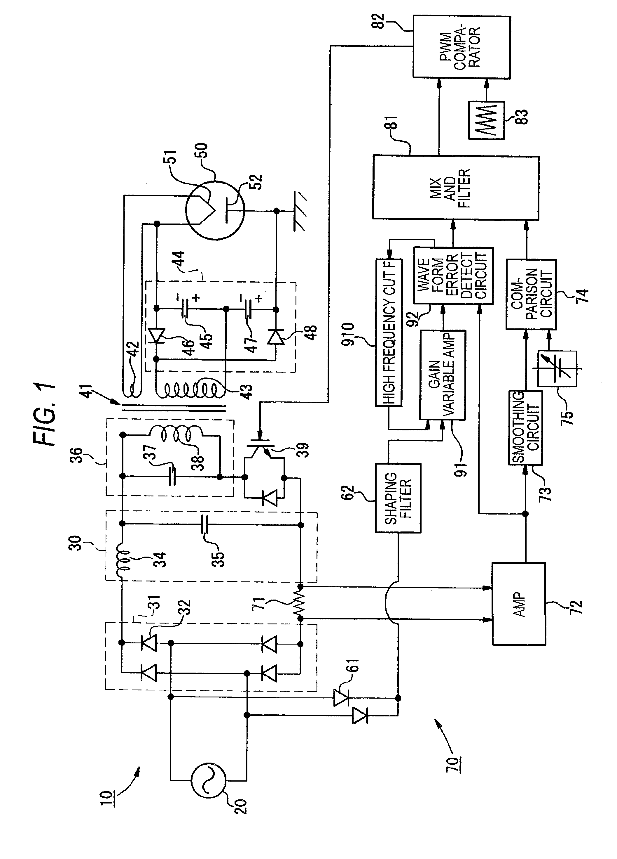
[0090]FIG. 1 is an explanatory block diagram of a high frequency heating apparatus according to an embodiment 1 of the invention. In FIG. 1, the high frequency heating apparatus is composed of an inverter main circuit 10, a control circuit 70 for controlling a switching transistor 39 of the inverter main circuit 10, and a magnetron 50. The inverter main circuit 10 includes an alternating current power supply 20, a diode bridge type rectifier circuit 31, a smoothing circuit 30, a resonance circuit 36, a switching transistor 39, and a voltage doubler rectifier circuit 44.

[0091]The alternating voltage of the alternating current power supply 20 is rectified by the diode bridge type rectifier circuit 31 composed of four diodes 32 and is converted to a direct voltage through the smoothing circuit 30 which is composed of an inductor 34 and a capacitor 35. After then, the direct voltage is converted to a high frequency alternating current by the resonance circuit36, which is composed of a c...

embodiment 2

[0115]According to the embodiment 2, in the wave form error detect circuit 92, there is additionally provided a limiter for limiting the difference information (wave form error signal) in the positive and negative directions thereof, whereby the difference information is input to the mix circuit 81 through the limiter. Now, FIG. 5 is an explanatory view of the present embodiment. Specifically, FIG. 5A is a block diagram of the present embodiment, FIG. 5B is a characteristic view thereof, and FIG. 5C is a wave form view thereof. In FIG. 5A, reference numeral 921 designates a limit function which is disposed in the wave form error detect circuit 92 according to the present embodiment. When the reference wave form from the gain variable amplifier circuit 91 and the input current wave form from the rectifier circuit 72 are input to the input of the wave form error detect circuit 92, a wave form error is output through this limit function 921 to the mix circuit 81.

[0116]Referring to FIG....

embodiment 3

[0121]According to the embodiment 3 of the invention, to the current control output, there is added a Vc limiter function which controls the collector voltage Vc of the switching transistor to a given value.

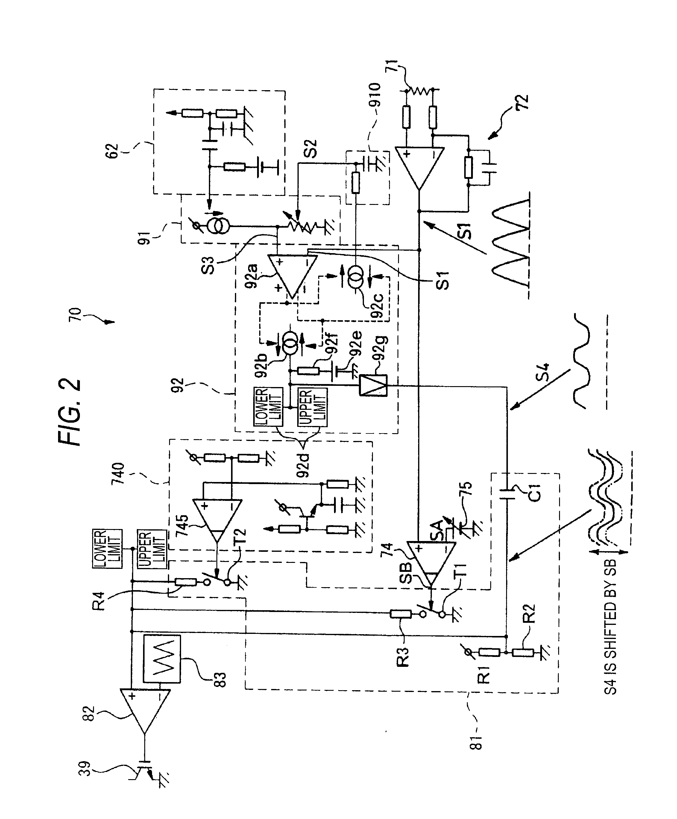
[0122]FIG. 6 is an explanatory view of a structure for adding the Vc limiter function to the current control output according to the embodiment 3. In this structure, to the circuit shown in FIG. 1, there is further added a comparator 740 which is shown by a dotted line in the lower portion of FIG. 6. This structure is shown in FIG. 2.

[0123]To one input terminal 742 of a comparator 745 of the comparator 740, there is input the collector voltage signal Vc of the switching transistor; and, to the other input terminal 743, there is input an applied voltage in the non-oscillating time of the magnetron as a voltage reference signal V2. A difference between the voltage signal Vc of the input terminal 742 and the voltage reference signal of the input terminal 743 is output from the compa...


PUM


Abstract

The object of the invention is not only to simplify the structure of a high frequency dielectric heating power control apparatus and reduce the size of the apparatus but also to eliminate the need for control and design corresponding to the kind of a magnetron and thus enhance the running efficiency of the apparatus.
An input current to an inverter circuit is detected by a shunt resistor 71 and is converted to an input current wave form through an input current signal amplifier 72. On the other hand, based on an alternating current power supply voltage wave form from an alternating power supply voltage, there is obtained through a gain variable amplifier 91 a reference wave form following the size of the input current wave form. A wave form error detect circuit 92 compares the input current wave form with the reference wave form to obtain a wave form error signal. A comparison circuit 74 compares the input current wave form with an input current reference signal obtained from an output setting part 75 for obtaining a desired high frequency output to thereby obtain a current error signal. And, a mix and filter circuit 81 adds the wave form error signal and the current error signal to obtain a power control signal for driving a switching transistor 39 of the inverter circuit. Here, the reference wave form is generated based only on the alternating current power supply voltage wave form and on the feedback signal of the wave form error signal.

Description

TECHNICAL FIELD[0001]The present invention relates to high frequency dielectric heating employed, for example, in a microwave oven using a magnetron and, specifically, the invention relates to high frequency dielectric heating which is free from variations in the characteristics of the magnetron, the kinds of magnetrons, and variations in the temperature of the anode of a magnetron.BACKGROUND ART[0002]Conventionally, in a high frequency heating apparatus, power to be supplied to a magnetron is controlled by the output pulse width of an inverter control circuit. According to the structure of the conventional apparatus, as the output voltage of signal superimposing means rises, the output pulse width of the inverter control circuit widens and power to be supplied to the magnetron increases. According to this structure, by varying the output voltage of the signal superimposing means, the heating output of the magnetron can be varied continuously.[0003]Also, since a heater also function...

Claims


Application Information

Patent Timeline
IPC IPC(8): H05B6/68
CPCH05B6/685H05B6/04
Inventor SUENAGA, HARUOYASUI, KENJI
Owner PANASONIC CORP
Why Eureka
Try Eureka